M15# MANUAL TRANSMISSION / TRANSAXLE MANUAL TRANSMISSION ASSEMBLY(for M152) INSTALLATION
PROCEDURE

 31111
1.INSTALL CLUTCH HOUSING
Install the clutch housing to the manual transmission assembly with the 9 bolts.
- Torque:
37 N*m (379 kgf*cm, 27 ft.*lbf)
31236B
2.INSTALL RELEASE FORK SUPPORT
Install the release fork support to the manual transmission assembly.
- Torque:
47 N*m (480 kgf*cm, 35 ft.*lbf)
31126
3.INSTALL CLUTCH RELEASE FORK BOOT
Install the clutch release fork boot to the manual transmission assembly.
31204
4.INSTALL CLUTCH RELEASE FORK SUB-ASSEMBLY
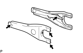
Apply release hub grease to the clutch release fork sub-assembly.

|
Release hub grease |
- Grease:
Toyota Genuine Release Hub Grease or equivalent
Engage the release bearing hub clip and install the clutch release fork sub-assembly to the clutch release bearing assembly.
31230
5.INSTALL CLUTCH RELEASE BEARING ASSEMBLY
Install the clutch release bearing assembly with the clutch release fork sub-assembly to the manual transmission assembly.
Install the clutch release fork sub-assembly to the release fork support.
- NOTICE:
-
After installation, move the fork back and forth to check that the release bearing slides smoothly.
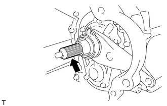
Apply clutch spline grease to the input shaft spline.
|
|
Clutch spline grease |
- Grease:
Toyota Genuine Clutch Spline Grease or equivalent
12325
6.INSTALL NO. 3 ENGINE MOUNTING BRACKET
Install the No. 3 engine mounting bracket to the manual transmission assembly with the 4 bolts.
- Torque:
44 N*m (449 kgf*cm, 32 ft.*lbf)
12321
7.INSTALL NO. 1 ENGINE MOUNTING BRACKET
Install the No. 1 engine mounting bracket to the manual transmission assembly with the 4 bolts.
- Torque:
44 N*m (449 kgf*cm, 32 ft.*lbf)
33110
8.INSTALL MANUAL TRANSMISSION ASSEMBLY (for LHD)
Support the manual transmission assembly with a transmission jack.
Install the manual transmission assembly.
- NOTICE:
- ·
Be careful not to pinch wire harnesses, etc.
·Do not forcefully pry on the manual transmission assembly.
·To avoid damage to the input shaft, do not forcefully shake the manual transmission assembly.
·Insert knock pins into the knock pin holes securely so that the end face of the manual transmission assembly fits close against the engine assembly before tightening the bolts.
Install the No. 1 transmission control cable bracket and 5 bolts.
- Torque:
72 N*m (730 kgf*cm, 53 ft.*lbf)
33110
9.INSTALL MANUAL TRANSMISSION ASSEMBLY (for RHD)
Support the manual transmission assembly with a transmission jack.
Install the manual transmission assembly.
- NOTICE:
- ·
Be careful not to pinch wire harnesses, etc.
·Do not forcefully pry on the manual transmission assembly.
·To avoid damage to the input shaft, do not forcefully shake the manual transmission assembly.
·Insert knock pins into the knock pin holes securely so that the end face of the manual transmission assembly fits close against the engine assembly before tightening the bolts.
Install the 5 bolts.
- Torque:
72 N*m (730 kgf*cm, 53 ft.*lbf)
51204
10.INSTALL NO. 3 FRAME CROSSMEMBER SUB-ASSEMBLY
Install the No. 3 frame crossmember sub-assembly to the engine mounting brackets with the 4 nuts and 4 washers.
- Torque:
56 N*m (571 kgf*cm, 41 ft.*lbf)
Install the No. 3 frame crossmember sub-assembly to the frame with the 12 bolts.
- Torque:
50 N*m (510 kgf*cm, 37 ft.*lbf)
33119
11.INSTALL STIFFENER PLATE LH
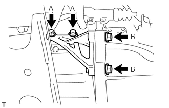
Install the stiffener plate LH to the manual transmission assembly with the 4 bolts.
- Torque:
- Bolt A:
69 N*m (700 kgf*cm, 51 ft.*lbf)
- Bolt B:
37 N*m (380 kgf*cm, 27 ft.*lbf)
33118
12.INSTALL STIFFENER PLATE RH
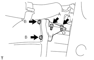
Install the stiffener plate RH to the manual transmission assembly with the 4 bolts.
- Torque:
- Bolt A:
69 N*m (700 kgf*cm, 51 ft.*lbf)
- Bolt B:
37 N*m (380 kgf*cm, 27 ft.*lbf)
13.CONNECT CONNECTOR
Connect the connectors and wire harness clamps to the manual transmission assembly.
28100
14.INSTALL STARTER ASSEMBLY
Install the starter assembly to the manual transmission assembly with the bolt, nut and 2 washers.
- Torque:
71 N*m (724 kgf*cm, 52 ft.*lbf)
Connect the terminal 50 connector to the starter assembly.
Connect the starter wire to the terminal 30 with the nut.
- Torque:
9.8 N*m (100 kgf*cm, 87 in.*lbf)
31470
15.INSTALL CLUTCH RELEASE CYLINDER ASSEMBLY
Install the clutch release cylinder assembly with the 2 bolts.
- Torque:
12 N*m (120 kgf*cm, 9 ft.*lbf)
33820B
16.CONNECT SHIFT AND SELECT TRANSMISSION CONTROL CABLE (for LHD)
Connect the shift and select transmission control cables to the manual transmission assembly with the 2 nuts and 2 new clips.
- Torque:
15 N*m (153 kgf*cm, 11 ft.*lbf)
33709F
17.INSTALL FLOOR SHIFT CROSS SHAFT SUB-ASSEMBLY (for RHD)
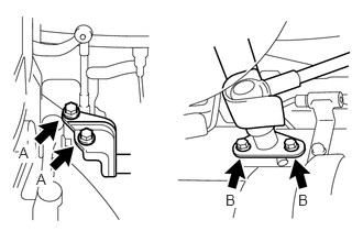
Install the floor shift cross shaft sub-assembly to the manual transmission assembly with the 4 bolts.
- Torque:
- Bolt A:
37 N*m (377 kgf*cm, 27 ft.*lbf)
- Bolt B:
18 N*m (184 kgf*cm, 13 ft.*lbf)
Connect the transmission side of the shift and select transmission control links with the 2 nuts.
- Torque:
15 N*m (153 kgf*cm, 11 ft.*lbf)
Connect the shift lever side of the shift and select transmission control links with the 2 nuts.
- Torque:
15 N*m (153 kgf*cm, 11 ft.*lbf)
46503C
18.INSTALL PARKING BRAKE PLATE SUB-ASSEMBLY
Clean the 4 bolts and their holes.
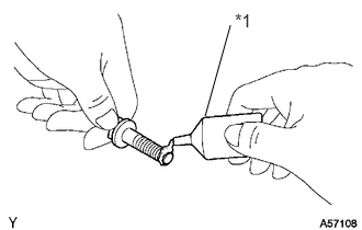
Apply adhesive to 2 or 3 threads on the end of the 4 bolts.
| *1 | Adhesive |
- Adhesive:
Toyota Genuine Adhesive 1324, Three Bond 1324 or equivalent
Install the parking brake plate sub-assembly to the manual transmission assembly with the 4 bolts.
- Torque:
47 N*m (474 kgf*cm, 34 ft.*lbf)
46501
19.INSTALL PARKING BRAKE DRUM SUB-ASSEMBLY
17410
20.INSTALL FRONT EXHAUST PIPE ASSEMBLY
w/o Exhaust Brake:
Install a new gasket.
Install the front exhaust pipe assembly to the exhaust manifold with 3 new nuts.
- Torque:
62 N*m (630 kgf*cm, 46 ft.*lbf)
Install the front exhaust pipe spacer to the exhaust pipe with the 4 bolts and 2 new gaskets.
- Torque:
23 N*m (235 kgf*cm, 17 ft.*lbf)
w/ Exhaust Brake:
Install a new gasket.
Install the front exhaust pipe assembly to the exhaust manifold with 3 new nuts.
- Torque:
62 N*m (630 kgf*cm, 46 ft.*lbf)
Install the exhaust retarder assembly to the exhaust pipe with the 4 bolts and 2 new gaskets.
- Torque:
23N*m{ 235kgf*cm , 17 ft.*lbf }
Connect the vacuum hose to the exhaust retarder assembly.
17571
21.INSTALL NO. 1 EXHAUST PIPE SUPPORT BRACKET
Install the No. 1 exhaust pipe support bracket to the manual transmission assembly with the 2 bolts.
- Torque:
35 N*m (360 kgf*cm, 26 ft.*lbf)
Tighten the clamp bolt.
- Torque:
23 N*m (230 kgf*cm, 17 ft.*lbf)
37110F
22.INSTALL PROPELLER SHAFT WITH CENTER BEARING ASSEMBLY
23.ADD MANUAL TRANSMISSION OIL
Park the vehicle in a level place.
Remove the filler plug and gasket.
Add manual transmission oil.
- Oil grade:
API GL-4
- Viscosity:
SAE 75W-90
- Capacity (Reference):
3.2 liters (3.4 US qts, 2.8 Imp. qts)
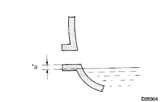
Check that the oil surface is within 5 mm (0.197 in.) below the lowest point of the filler plug opening.
| *a | 0 to 5 mm (0 to 0.197 in.) |
- NOTICE:
- ·
Problems may occur when the oil level is too high or too low.
·After replacing the oil, drive the vehicle and check the oil level again.
Install a new gasket and the filler plug.
- Torque:
37 N*m (379 kgf*cm, 27 ft.*lbf)
24.CONNECT CABLE TO NEGATIVE BATTERY TERMINAL
- Torque:
3.9 N*m (40 kgf*cm, 35 in.*lbf)
25.INSPECT FOR MANUAL TRANSMISSION OIL LEAK
26.INSPECT FOR EXHAUST GAS LEAK