SEAT REAR SEAT ASSEMBLY(for Tumble Type 4-Passenger Seat) REASSEMBLY
CAUTION / NOTICE / HINT
- CAUTION:
-
Wear protective gloves. Sharp areas on the parts may injure your hands.
PROCEDURE

 79806B
1.INSTALL REAR SEAT FOLD LEG SUB-ASSEMBLY
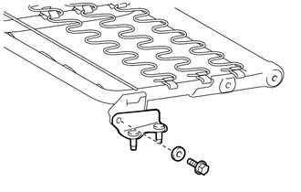
Install the rear seat fold leg sub-assembly with the bolt and washer.
- Torque:
37 N*m (377 kgf*cm, 27 ft.*lbf)
79086B
2.INSTALL NO. 8 SEAT CUSHION PAD SUB-ASSEMBLY LH
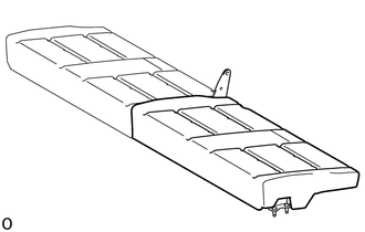
Install the No. 8 seat cushion pad sub-assembly LH onto the No. 8 seat cushion spring assembly.
79085B
3.INSTALL NO. 8 SEAT CUSHION PAD SUB-ASSEMBLY RH
- HINT:
-
Use the same procedure described for the LH side.
79081A
4.INSTALL NO. 8 SEAT CUSHION COVER SUB-ASSEMBLY
- HINT:
- ·
When installing the seat cover, refer to the precautions in order to prevent wrinkles from forming.
Click hereVehicle Interior>SEAT>FRONT SEAT ASSEMBLY>PRECAUTION
·Align the seam allowance in a single direction as shown in the illustration.
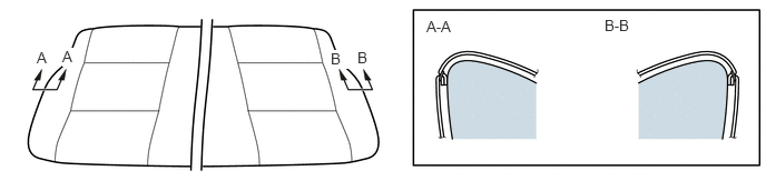 0.344,0.458 0.5,0.656 0.156,0.198 10 false A 0.583,0.448 0.771,0.625 0.188,0.177 10 true A 3.344,0.458 3.5,0.656 0.156,0.198 10 false B 3.094,0.469 3.281,0.646 0.188,0.177 10 true B 3.99,0.167 4.438,0.365 0.448,0.198 10 false A-A 5.656,0.156 6.104,0.354 0.448,0.198 10 false B-B
Set the No. 8 seat cushion cover sub-assembly to both sides of the No. 8 seat cushion pad.
Using hog ring pliers, install the No. 8 seat cushion cover sub-assembly to both sides of the No. 8 seat cushion pad with 24 new hog rings in the order shown in the illustration.
- NOTICE:
- ·
Do not dirty or damage the No. 8 seat cushion cover sub-assembly.
·Be sure to securely install the hog rings as shown in the illustration while preventing wrinkles from forming on the No. 8 seat cushion cover sub-assembly.
- HINT:
-
Install the hog rings at the cutouts if they are there.
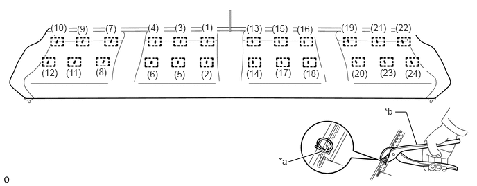 5.938,1.688 6.104,1.688 6.104,1.688 6.26,2.177 false 4.333,2.438 4.833,2.281 true 3.031,0.323 3.26,0.531 0.229,0.208 10 true (1) 3.021,1.031 3.26,1.229 0.24,0.198 10 true (2) 2.625,0.333 2.865,0.531 0.24,0.198 10 true (3) 2.208,1.031 2.448,1.229 0.24,0.198 10 true (6) 2.615,1.031 2.854,1.229 0.24,0.198 10 true (5) 1.583,0.344 1.823,0.542 0.24,0.198 10 true (7) 1.438,1 1.677,1.198 0.24,0.198 10 true (8) 1.156,0.354 1.396,0.552 0.24,0.198 10 true (9) 0.76,0.333 1.042,0.531 0.281,0.198 10 true (10) 0.99,1.01 1.271,1.208 0.281,0.198 10 true (11) 0.625,1.01 0.906,1.208 0.281,0.198 10 true (12) 3.698,1.021 4.01,1.219 0.313,0.198 10 true (14) 3.698,0.344 3.979,0.542 0.281,0.198 10 true (13) 4.083,0.344 4.396,0.542 0.313,0.198 10 true (15) 4.458,0.354 4.771,0.552 0.313,0.198 10 true (16) 4.135,1.01 4.448,1.208 0.313,0.198 10 true (17) 4.552,1.021 4.865,1.219 0.313,0.198 10 true (18) 5.125,0.333 5.438,0.531 0.313,0.198 10 true (19) 5.281,1.021 5.594,1.219 0.313,0.198 10 true (20) 5.563,0.333 5.875,0.531 0.313,0.198 10 true (21) 5.938,0.333 6.25,0.531 0.313,0.198 10 true (22) 5.708,1.01 6.021,1.208 0.313,0.198 10 true (23) 6.083,1.021 6.396,1.219 0.313,0.198 10 true (24) 5.771,1.594 6.083,1.792 0.313,0.198 10 false *b 4.188,2.344 4.5,2.542 0.313,0.198 10 false *a 2.219,0.333 2.458,0.531 0.24,0.198 10 true (4)
Text in Illustration *a Cutout *b Hog Ring Pliers
Using hog ring pliers, install the No. 8 seat cushion cover sub-assembly to the No. 8 seat cushion spring assembly with 30 new hog rings in the order shown in the illustration.
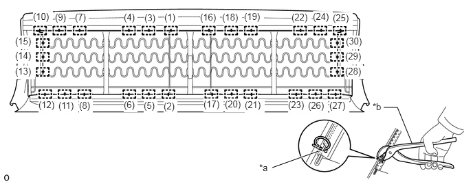
| *a | Cutout | *b | Hog Ring Pliers |
- NOTICE:
- ·
Be careful not to damage the No. 8 seat cushion cover sub-assembly.
·Be sure to securely install the hog rings as shown in the illustration while preventing wrinkles from forming on the No. 8 seat cushion cover sub-assembly.
- HINT:
-
Install the hog rings at the cutouts if they are there.
78970
5.INSTALL SEAT LOCK BAND ASSEMBLY
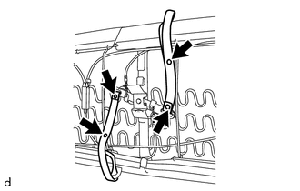
Using a pliers, swage 4 new seat turn lock guide pins to install the 2 seat lock band assemblies.
- NOTICE:
-
Be careful not to damage the seat turn lock guide pins.
78960
6.INSTALL NO. 2 FOLD SEAT STOPPER BAND ASSEMBLY
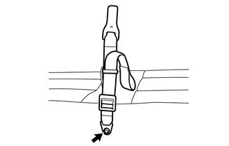
Install the No. 2 fold seat stopper band assembly with the screw.
79886
7.INSTALL FOLD SEATBACK SET HINGE
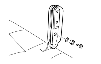
Install both sides of the fold seatback set hinge with the bolt, washer and bush.
- Torque:
37 N*m (377 kgf*cm, 27 ft.*lbf)
8.INSTALL INNER NO. 1 QUARTER PROTECTOR
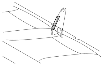
Install the inner No. 1 quarter protector.
- HINT:
-
Install the fold seatback set hinges on both sides in a position where there is no interference with operation.
73580B
9.INSTALL REAR SEAT INNER BELT ASSEMBLY RH (w/ Seat Belt)
73590A
10.INSTALL REAR SEAT INNER BELT ASSEMBLY LH (w/ Seat Belt)
- HINT:
-
Use the same procedure described for the RH side.
73030A
11.INSTALL REAR SEAT LAP TYPE BELT ASSEMBLY RH (w/ Seat Belt)
73040A
12.INSTALL REAR SEAT LAP TYPE BELT ASSEMBLY LH (w/ Seat Belt)
- HINT:
-
Use the same procedure described for the RH side.
79088B
13.INSTALL NO. 8 SEATBACK PAD SUB-ASSEMBLY LH
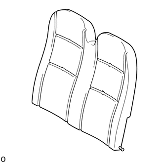
Install the No. 8 seatback pad sub-assembly LH onto the No. 8 seatback frame sub-assembly LH.
79087B
14.INSTALL NO. 8 SEATBACK PAD SUB-ASSEMBLY RH
- HINT:
-
Use the same procedure described for the LH side.
79084
15.INSTALL NO. 8 SEATBACK COVER SUB-ASSEMBLY LH
- HINT:
- ·
When installing the seat cover, refer to the precautions in order to prevent wrinkles from forming.
Click hereVehicle Interior>SEAT>FRONT SEAT ASSEMBLY>PRECAUTION
·Align the seam allowance in a single direction as shown in the illustration.
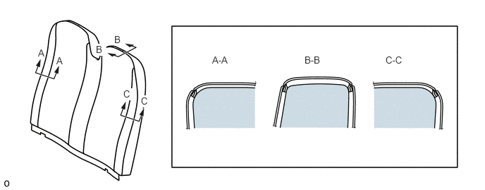 0.563,0.698 0.719,0.875 0.156,0.177 10 false A 0.833,0.813 0.99,0.99 0.156,0.177 10 false A 1.417,0.646 1.573,0.823 0.156,0.177 10 true B 1.688,0.5 1.844,0.677 0.156,0.177 10 true B 1.823,1.302 1.979,1.479 0.156,0.177 10 true C 2.083,1.406 2.24,1.583 0.156,0.177 10 true C 3.135,0.802 3.594,1 0.458,0.198 10 false A-A 4.5,0.802 4.958,1 0.458,0.198 10 false B-B 5.698,0.802 6.156,1 0.458,0.198 10 false C-C
Set the No. 8 seatback cover sub-assembly LH to the No. 8 seatback pad sub-assembly LH.
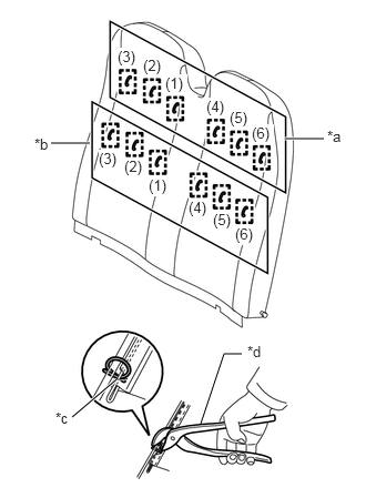
Using hog ring pliers, install the upper side of the No. 8 seatback cover sub-assembly LH with 6 new hog rings in the order shown in the illustration.
| *a | Upper Side Hog Ring |
| *b | Lower Side Hog Ring |
| *c | Cutout |
| *d | Hog Ring Pliers |
- NOTICE:
- ·
Do not dirty or damage the No. 8 seatback cover sub-assembly.
·Be sure to securely install the hog rings as shown in the illustration while preventing wrinkles from forming on the No. 8 seatback pad sub-assembly.
- HINT:
-
Install the hog rings at the cutouts if they are there.
Using hog ring pliers, install the lower side of the No. 8 seatback cover sub-assembly LH with 6 new hog rings in the order shown in the illustration.
- NOTICE:
- ·
Do not dirty or damage the No. 8 seatback cover sub-assembly.
·Be sure to securely install the hog rings as shown in the illustration while preventing wrinkles from forming on the No. 8 seatback pad sub-assembly.
- HINT:
-
Install the hog rings at the cutouts if they are there.
Close the fastener.
Attach the hook.
79083
16.INSTALL NO. 8 SEATBACK COVER SUB-ASSEMBLY RH
- HINT:
-
Use the same procedure described for the LH side.
17.INSTALL NO. 8 SEATBACK ASSEMBLY LH
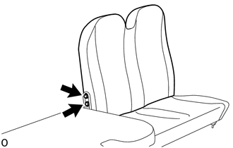
Install the No. 8 seatback assembly LH with the 2 bolts.
- Torque:
37 N*m (377 kgf*cm, 27 ft.*lbf)
18.INSTALL NO. 8 SEATBACK ASSEMBLY RH
- HINT:
-
Use the same procedure described for the LH side.
19.INSTALL FOLD SEAT LOCK ASSEMBLY LH
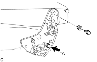
w/o Seat Belt:
Install the fold seat lock assembly LH with the 2 bolts and bush.
- Torque:
37 N*m (377 kgf*cm, 27 ft.*lbf)
| *A | w/o Seat Belt |
w/ Seat Belt:
Install the fold seat lock assembly LH with the bolt and bush.
- Torque:
37 N*m (377 kgf*cm, 27 ft.*lbf)
20.INSTALL FOLD SEAT LOCK ASSEMBLY RH
- HINT:
-
Use the same procedure described for the LH side.
78930
21.INSTALL NO. 3 FOLD SEAT LOCK CONTROL CABLE ASSEMBLY
Set the No. 3 fold seat lock control cable assembly in place.
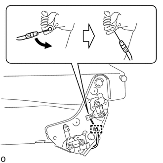
Connect and rotate the cable end.
Attach the cable clamp.
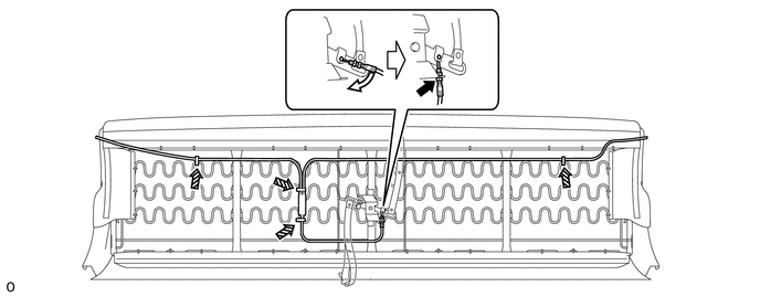
Use the same procedure for the other cable end.
Connect and rotate the cable end.
Tighten the lock nut.
Install the 4 cable clamps.

|
Lock Nut | 
|
Cable Clamp |
78910
22.INSTALL NO. 1 FOLD SEAT LOCK CONTROL CABLE ASSEMBLY
Set the No. 1 fold seat lock control cable assembly in place.
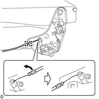
Connect and rotate the cable end.
Attach the cable clamp.
Use the same procedure for the other cable end.
Connect and rotate the cable end.
Tighten the lock nut.
Install the 4 cable clamps.
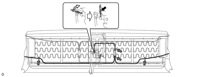
|
|
Lock Nut |
|
Cable Clamp |
78950
23.INSTALL NO. 1 FOLD SEAT STOPPER BAND ASSEMBLY
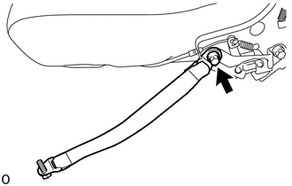
Install the No. 1 fold seat stopper band assembly with the bolt.
- Torque:
37 N*m (377 kgf*cm, 27 ft.*lbf)
- HINT:
-
Use the same procedure to install the No. 1 fold seat stopper band assembly on the other side.
73307
24.INSTALL REAR SEAT INNER BELT SUB-ASSEMBLY (w/ Seat Belt)
72666B
25.INSTALL REAR SEAT LOCK COVER LH
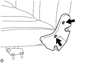
Install the rear seat lock cover LH with the 2 screws.
72665C
26.INSTALL REAR SEAT LOCK COVER RH
- HINT:
-
Use the same procedure described for the LH side.