SUPPLEMENTAL RESTRAINT SYSTEMS AIRBAG ECU INSTALLATION
CAUTION / NOTICE / HINT
- HINT:
- ·
Use the same procedure for RHD and LHD vehicles.
·The procedure listed below is for LHD vehicles.
·A bolt without a torque specification is shown in the standard bolt chart (Click hereGeneral>SPECIFICATIONS>STANDARD BOLT>SPECIFIED TORQUE FOR STANDARD BOLTS).
PROCEDURE

 89170A
1.INSTALL AIRBAG ECU ASSEMBLY
Check that the ignition switch is off.
Check that the cable is disconnected from the negative (-) battery terminal.
- CAUTION:
-
Wait at least 90 seconds after disconnecting the cable from the negative (-) battery terminal to disable the SRS system.
Check that the waterproof sheet is properly set.
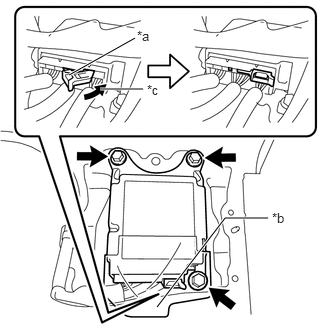
Install the airbag ECU assembly with the 3 bolts.
- Torque:
17.5N*m{ 178kgf*cm , 13 ft.*lbf }
- NOTICE:
- ·
If the airbag ECU assembly has been dropped, or there are any cracks, dents or other defects in the case or connector, replace the airbag ECU assembly with a new one.
·When installing the airbag ECU assembly, be careful that the SRS wiring does not interfere with or is not pinched between other parts.
·When the ignition switch is first turned to ON after the airbag ECU assembly has been replaced, make sure that no one is in the vehicle.
| *a | Connector Lock Lever |
| *b | Waterproof Sheet |
| *c | Lock in this Direction |
Connect the airbag connector and push the connector lock lever to lock the airbag connector.
- NOTICE:
- ·
When connecting the airbag connector, take care not to damage the airbag wire harness.
·Do not allow the water proof sheet to become pinched.
Check that there is no looseness in the installation parts of the airbag ECU assembly.
51771J
2.INSTALL STEP
Install the step with the 4 bolts.
51774C
3.INSTALL STEP PLATE COVER
for Type A, Type B:
Install the step plate cover with the 4 bolts.
for Type C:
Install the step plate cover with the 3 bolts.
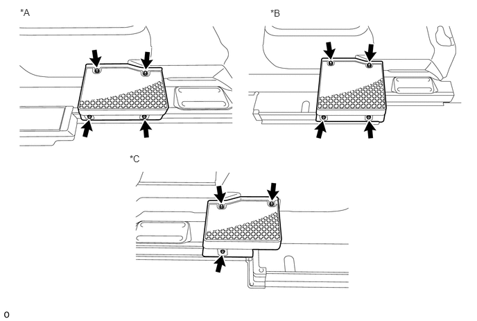
| *A | for Type A | *B | for Type B |
| *C | for Type C | - | - |
4.CONNECT CABLE TO NEGATIVE BATTERY TERMINAL
- NOTICE:
-
When disconnecting the cable, some systems need to be initialized after the cable is reconnected (Click here).
Click hereGeneral>INTRODUCTION>REPAIR INSTRUCTION>INITIALIZATION
5. PERFORM DIAGNOSTIC SYSTEM CHECK
for 2 Connectors Type:
for 3 Connectors Type:
6. CHECK SRS WARNING LIGHT
for 2 Connectors Type:
for 3 Connectors Type:
7. PERFORM YAW RATE AND ACCELERATION SENSOR ZERO POINT CALIBRATION (w/ Multi-information Display)
When the airbag ECU assembly is replaced, perform zero point learning for the yaw rate and acceleration sensor (Click hereBrake>BRAKE CONTROL / DYNAMIC CONTROL SYSTEMS>ANTI-LOCK BRAKE SYSTEM(w/ Brake pedal Load Sensing Switch)>CALIBRATION).
- HINT:
-
The yaw rate and acceleration sensor is built into the airbag ECU assembly.