1BZ-FPE ENGINE MECHANICAL TIMING GEAR REMOVAL
PROCEDURE

 1.REMOVE DRIVE BELTS, FAN, FLUID COUPLING ASSEMBLY AND WATER PUMP PULLEY
17141
2.REMOVE EXHAUST MANIFOLD
19901A
3.DISCONNECT HIGH-TENSIONCORDS FROM SPARK PLUGS
19100
4.REMOVE DISTRIBUTOR
19100P
5.REMOVE SPARK PLUGS
11201
6.REMOVE CYLINDER HEAD COVER
13901
7.REMOVE VALVE ROCKER SHAFT ASSEMBLY
8.REMOVE PUSH RODS
13751
9.DISPLACE VALVE LIFTERS
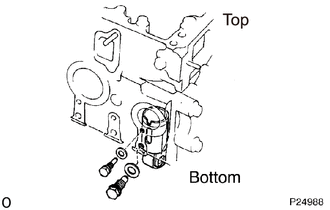
Remove bolts (A), (B) and gaskets.
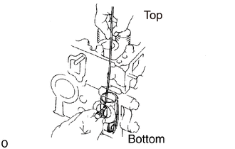
Using a wire, lift up the valve lifter until long hole (C) of the valve lifter moves up to the position of the installation hole for bolt (A).
- HINT:
-
If the lifter is lifted up too high it may get out of position.
Install bolt (A).
Check that bolt (A) prevents the valve lifter form falling.
- NOTICE:
-
Be careful not to scratch the valve lifter.
13470
10.REMOVE CRANKSHAFT PULLEY
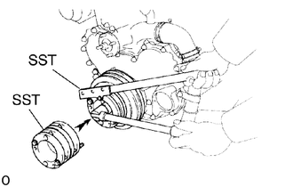
Using SST, remove the mount bolt.
- SST
- 09213-58014 (90105-08076)
09330-00021
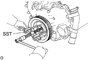
Using SST, remove the pulley.
- SST
- 09950-50013 (09951-05010, 09952-05010, 09953-05010, 09953-05020, 09954-05031)
16577C
11.REMOVE RADIATOR PIPE
Remove the 2 bolts holding the radiator pipe to the timing belt cover.
Disconnect the radiator hose from the water pump, and remove the radiator pipe.
15301
12.REMOVE OIL DIPSTICK AND GUIDE
19971G
13.REMOVE VACUUM PIPE
11302Q
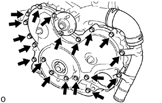
14.REMOVE TIMING GEAR COVER
Remove the 15 mount bolts and bracket.
Using a plastic-faced hammer, lightly tap out the gear cover.
Remove the cover gasket.
15.REMOVE INJECTION PUMP DRIVE GEAR FROM TIMING GEAR COVER
Using a plastic-faced hammer, lightly tap out the gear and remove the drive gear.
29300
16.REMOVE VACUUM PUMP
Remove the 2 bolts and vacuum pump.
Remove the 2 O-rings.
17.CHECK IDLE GEAR THRUST CLEARANCE
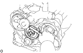
Using a feeler gauge, measure the idle gear thrust clearance.
- Standard thrust clearance:
0.060 - 0.170 mm (0.0024 - 0.0067 in.)
- Maximum thrust clearance:
0.30 mm (0.0118 in.)
If the thrust clearance is greater than maximum, replace the thrust plate.
13525
18.REMOVE IDLE GEAR
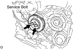
Secure the idler sub-gears to the idler gear with a service bolt.
| Thread diameter | 6 mm |
| Thread pitch | 1.0 mm |
| Bolt length | 25.0 mm (0.98 in.) |
Remove the 2 bolts, thrust plate and idle gear.
13503
19.REMOVE IDLE GEAR SHAFT
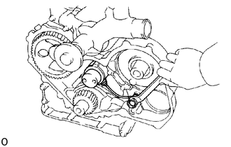
Remove the union bolt and idle gear shaft.
13523
20.REMOVE CAMSHAFT TIMING GEAR AND CAMSHAFT ASSEMBLY
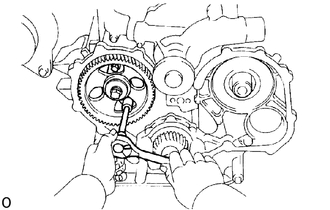
Remove the 2 bolts holding the thrust plate to the cylinder block.
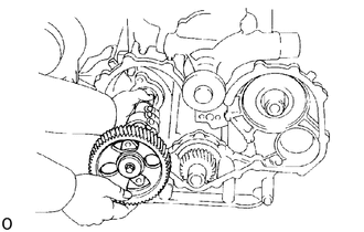
Carefully pull out the camshaft and timing gear assembly.
- NOTICE:
-
Be careful not to damage the camshaft bearing.
13521
21.REMOVE CRANKSHAFT TIMING GEAR
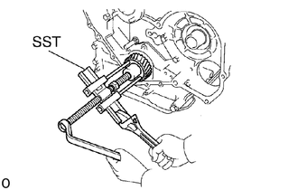
Using SST, remove the timing gear.
- SST
- 09950-50013 (09951-05010, 09952-05010, 09953-05010, 09953-05020, 09954-05031)