RM2850E
_58
Vehicle Interior
_073208
LIGHTING
_0356326
TURN SIGNAL FLASHER ASSEMBLY
G
LIGHTING TURN SIGNAL FLASHER ASSEMBLY ON-VEHICLE INSPECTION
PROCEDURE

 81980
1.INSPECT TURN SIGNAL FLASHER ASSEMBLY
a.
Remove the turn signal flasher assembly.
Click hereVehicle Interior>LIGHTING>TURN SIGNAL FLASHER ASSEMBLY>REMOVAL
b.
1.448,0.26 1.813,0.469
0.365,0.208
0.667,0.938 1.073,0.938
true
0.906,1.625 1.094,1.24
true
1.74,1.635 1.927,1.25
true
0.167,0.125 0.615,0.458
0.448,0.333
10
false
*a
0.458,0.865 0.906,1.198
0.448,0.333
10
false
IG
0.802,1.656 1.25,1.99
0.448,0.333
10
false
B
1.688,1.677 2.135,2.01
0.448,0.333
10
false
E
1.521,0.281 1.969,0.615
0.448,0.333
10
false
J40
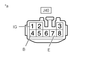
Measure the resistance and voltage on the wire harness side connector according to the value(s) in the table below.
- Standard Resistance:
Tester Connection Condition Specified Condition J40-7(E) - Body ground Always Below 1 Ω
- Standard Resistance:
Tester Connection Condition Specified Condition J40-4(B) - J40-7(E) Always 11 to 14 V J40-1(IG) - J40-7(E) IG ON
If the result is not as specified, repair or replace the wire harness or connector.
| *a | Front view of wire harness connector
(to Turn Signal Flasher Assembly) |
c.
Connect the connector.
d.
1.396,0.24 1.792,0.458
0.396,0.219
1.115,0.833 0.698,0.833
true
1.917,0.813 2.094,0.365
true
1.104,1.229 0.833,1.542
true
1.969,1.25 2.208,1.719
true
1.583,1.24 1.375,1.75
true
1.333,1.24 1.073,1.667
true
0.073,0.052 0.365,0.375
0.292,0.323
10
false
*a
2.146,0.198 2.635,0.469
0.49,0.271
10
false
LR
0.49,0.75 0.875,0.969
0.385,0.219
10
false
LL
0.49,1.469 1.073,1.74
0.583,0.271
10
false
HAZ
0.969,1.698 1.292,1.969
0.323,0.271
10
false
E
1.292,1.813 1.646,2.01
0.354,0.198
10
false
ER
2.177,1.771 2.552,1.979
0.375,0.208
10
false
EL
1.479,0.26 1.938,0.552
0.458,0.292
10
false
J40
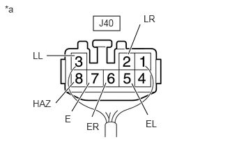
Measure the voltage according to the value(s) in the table below.
- Standard Voltage:
Tester Connection Condition Specified Condition J40-5(EL) - J40-7(E) IG ON Turn signal switch left OFF → ON 9 V or higher → 1.5 V or Below J40-6(ER) - J40-7(E) IG ON Turn signal switch right OFF → ON 9 V or higher → 1.5 V or Below J40-8(HAZ) - J40-7(E) Hazard warning switch OFF → ON 9 V or higher → 1.5 V or Below J40-2(LR) - J40-7(E) IG ON Turn signal switch right OFF → ON 1.5 V or Below → 1.5 V or Below ←→ 9 V or higher (75 to 95 times per minute) Hazard warning switch OFF → ON J40-3(LL) - J40-7(E) IG ON Turn signal switch left OFF → ON 1.5 V or Below → 1.5 V or Below ←→ 9 V or higher (75 to 95 times per minute) Hazard warning switch OFF → ON
If the result is not as specified, replace the turn signal flasher assembly.
| *a | Component with harness connected
(Turn Signal Flasher Assembly) |