BRAKE CONTROL / DYNAMIC CONTROL SYSTEMS VEHICLE STABILITY CONTROL SYSTEM C144C Brake Booster Pressure Sensor "B" Circuit Low C144D Brake Booster Pressure Sensor "B" Circuit High C145A Brake Booster Pressure Sensor "B" Power Supply Circuit C1476 Brake Booster Pressure Sensor Circuit Low C1477 Brake Booster Pressure Sensor Circuit High C1479 Abnormal Power Supply Voltage in Brake Booster Pressure Sensor
DESCRIPTION
The No. 1 vacuum booster pressure sensor (vacuum sensor assembly) and No. 2 vacuum booster pressure sensor (vacuum sensor assembly) detect pressure in the brake booster.
When a malfunction occurs in the No. 1 vacuum booster pressure sensor (vacuum sensor assembly) and No. 2 vacuum booster pressure sensor (vacuum sensor assembly), the fail-safe prohibits ABS and brake pressure increase function control and illuminates the ABS warning light.
- HINT:
-
EBD control will continue to the extent that EBD control is possible even after ABS is prohibited.
| DTC No. | DTC Detection Condition | Trouble Area |
|---|---|---|
| C144C | When the No. 2 vacuum booster pressure sensor power source voltage is between 4.8 and 5.2 V and the No. 2 vacuum booster pressure sensor input voltage is less than 0.39 V for 1.2 seconds or more continuously. | ·
No. 2 vacuum booster pressure sensor (vacuum sensor assembly) ·
Wire harness or connector ·
Skid control ECU (brake actuator assembly) |
| C144D | When the No. 2 vacuum booster pressure sensor power source voltage is between 4.8 and 5.2 V and the No. 2 vacuum booster pressure sensor input voltage is higher than 4.41 V for 1.2 seconds or more continuously. | ·
No. 2 vacuum booster pressure sensor (vacuum sensor assembly) ·
Wire harness or connector ·
Skid control ECU (brake actuator assembly) |
| C145A | When the +BS terminal voltage is between 9.5 and 17.4 V and the No. 2 vacuum booster pressure sensor power source voltage exceeds 5.2 V or is below 4.8 V for 1.2 seconds or more continuously. | ·
No. 2 vacuum booster pressure sensor (vacuum sensor assembly) ·
Wire harness or connector ·
Skid control ECU (brake actuator assembly) |
| C1476 | When the No. 1 vacuum booster pressure sensor power source voltage is between 4.8 and 5.2 V and the No. 1 vacuum booster pressure sensor input voltage is less than 0.39 V for 1.2 seconds or more continuously. | ·
No. 1 vacuum booster pressure sensor (vacuum sensor assembly) ·
Wire harness or connector ·
Skid control ECU (brake actuator assembly) |
| C1477 | When the No. 1 vacuum booster pressure sensor power source voltage is between 4.8 and 5.2 V and the No. 1 vacuum booster pressure sensor input voltage is higher than 4.41 V for 1.2 seconds or more continuously. | ·
No. 1 vacuum booster pressure sensor (vacuum sensor assembly) ·
Wire harness or connector ·
Skid control ECU (brake actuator assembly) |
| C1479 | When the +BS terminal voltage is between 9.5 and 17.4 V and the No. 1 vacuum booster pressure sensor power source voltage exceeds 5.2 V or is below 4.8 V for 1.2 seconds or more continuously. | ·
No. 1 vacuum booster pressure sensor (vacuum sensor assembly) ·
Wire harness or connector ·
Skid control ECU (brake actuator assembly) |
WIRING DIAGRAM
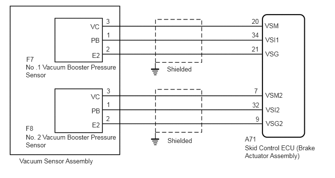
CAUTION / NOTICE / HINT
- NOTICE:
-
When replacing the skid control ECU (brake actuator assembly), perform calibration and store system information (Click hereBrake>BRAKE CONTROL / DYNAMIC CONTROL SYSTEMS>VEHICLE STABILITY CONTROL SYSTEM>CALIBRATION).
PROCEDURE
Make sure that there is no looseness at the locking part and the connecting part of the connectors.
Disconnect the A71 skid control ECU (brake actuator assembly) connector.
Disconnect the F7 and F8 vacuum sensor assembly connectors.
Measure the resistance according to the value(s) in the table below.
- Standard Resistance:
- No. 1 Vacuum Booster Pressure Sensor:
Tester Connection Condition Specified Condition A71-20 (VSM) - F7-3 (VC) Always Below 1 Ω A71-20 (VSM) or F7-3 (VC) - Body ground Always 10 kΩ or higher A71-34 (VSI1) - F7-1 (PB) Always Below 1 Ω A71-34 (VSI1) or F7-1 (PB) - Body ground Always 10 kΩ or higher A71-21 (VSG) - F7-2 (E2) Always Below 1 Ω A71-21 (VSG) or F7-2 (E2) - Body ground Always 10 kΩ or higher
- No. 2 Vacuum Booster Pressure Sensor:
Tester Connection Condition Specified Condition A71-7 (VSM2) - F8-3 (VC) Always Below 1 Ω A71-7 (VSM2) or F8-3 (VC) - Body ground Always 10 kΩ or higher A71-32 (VSI2) - F8-1 (PB) Always Below 1 Ω A71-32 (VSI2) or F8-1 (PB) - Body ground Always 10 kΩ or higher A71-9 (VSG2) - F8-2 (E2) Always Below 1 Ω A71-9 (VSG2) or F8-2 (E2) - Body ground Always 10 kΩ or higher
- Result:
Proceed to OK NG
OK
NG
Reconnect the A71 skid control ECU (brake actuator assembly) connector.
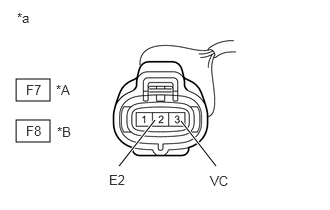
Measure the voltage according to the value(s) in the table below.
- Standard Voltage:
- No. 1 Vacuum Booster Pressure Sensor:
Tester Connection Condition Specified Condition F7-3 (VC) - F7-2 (E2) Ignition switch ON 4.75 to 5.25 V
- No. 2 Vacuum Booster Pressure Sensor:
Tester Connection Condition Specified Condition F8-3 (VC) - F8-2 (E2) Ignition switch ON 4.75 to 5.25 V
| *A | No. 1 Vacuum Booster Pressure Sensor |
| *B | No. 2 Vacuum Booster Pressure Sensor |
| *a | Front view of wire harness connector
(to Vacuum Sensor Assembly) |
- Result:
Proceed to OK NG
OK
NG
Remove the vacuum sensor assembly (Click hereBrake>BRAKE CONTROL / DYNAMIC CONTROL SYSTEMS>VACUUM SENSOR>REMOVAL).
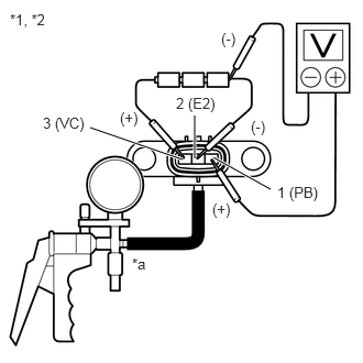
Connect 3 dry batteries of 1.5 V in series.
Connect 3 (VC) terminal to the batteries' positive (+) terminal, and 2 (E2) terminal to the batteries' negative (-) terminal, apply about 4.5 V between 3 (VC) and 2 (E2) terminals.
- NOTICE:
-
Do not apply voltage of 6 V or more to terminals 3 (VC) and 2 (E2).
Connect a voltmeter to terminals 1 (PB) and 2 (E2) of the No. 1 vacuum booster pressure sensor and No. 2 vacuum booster pressure sensor, and measure the output voltage under ambient atmospheric pressure.
Apply vacuum to the vacuum booster pressure sensor in segments from 13.3 kPa (100 mmHg, 3.94 in.Hg) to 66.7 kPa (500 mmHg, 19.69 in.Hg).
Measure the voltage according to the value(s) in the table below.
- Standard Voltage:
- No. 1 Vacuum Booster Pressure Sensor, No. 2 Vacuum Booster Pressure Sensor:
Tester Connection Condition (Applied Vacuum) Specified Condition 1 (PB) - 2 (E2) 13.3 kPa (100 mmHg, 3.94 in.Hg) 0.26 to 0.46 V 26.7 kPa (200 mmHg, 7.87 in.Hg) 0.62 to 0.82 V 40.0 kPa (300 mmHg, 11.81 in.Hg) 0.98 to 1.18 V 53.5 kPa (400 mmHg, 15.75 in.Hg) 1.34 to 1.54 V 66.7 kPa (500 mmHg, 19.69 in.Hg) 1.7 to 1.9 V
| *1 | No. 1 Vacuum Booster Pressure Sensor |
| *2 | No. 2 Vacuum Booster Pressure Sensor |
| *a | Vacuum |
- Result:
Proceed to OK NG
OK
NG