2TR-FE CHARGING GENERATOR(for 80A Type) REMOVAL
PROCEDURE

 1. PRECAUTION
- NOTICE:
-
After turning the ignition switch off, waiting time may be required before disconnecting the cable from the negative (-) battery terminal. Therefore, make sure to read the disconnecting the cable from the negative (-) battery terminal notices before proceeding with work (Click here General>INTRODUCTION>REPAIR INSTRUCTION>PRECAUTION ).
2.DISCONNECT CABLE FROM NEGATIVE BATTERY TERMINAL
- NOTICE:
-
When disconnecting the cable, some systems need to be initialized after the cable is reconnected (Click here General>INTRODUCTION>REPAIR INSTRUCTION>INITIALIZATION).
51405A
3.REMOVE NO. 1 ENGINE UNDER COVER
58410
4.REMOVE ENGINE SERVICE HOLE COVER
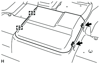
Detach the 2 hooks and 2 guides and remove the engine service hole main cover.
58734B
5.REMOVE REAR ENGINE SERVICE COVER WEATHERSTRIP
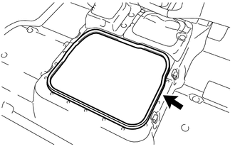
Remove the rear engine service cover weatherstrip.
58521D
6.REMOVE ENGINE SERVICE HOLE COVER MAT
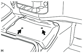
Remove the engine service hole cover mat.
58420
7.REMOVE NO. 2 ENGINE SERVICE HOLE COVER ASSEMBLY
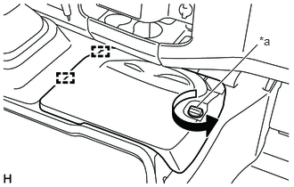
Turn the knob to detach the hook, detach the 2 guides and remove the No. 2 engine service hole cover assembly.
| *a | Knob |
58123A
8.REMOVE SHIFT AND SELECT LEVER SUPPORT WITH BOOTS
Remove the shift lever knob sub-assembly.
Remove the transmission cover mat.
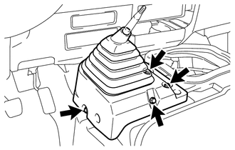
Remove the 4 bolts and remove the shift and select lever support with boots.
33506F
9.REMOVE FLOOR SHIFT CONTROL SHIFT LEVER RETAINER SUB-ASSEMBLY
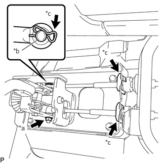
Remove the nut, washer plate, 3 clips and disconnect the select cable and the shift cable.
| *a | Knob |
| *b | Washer Plate |
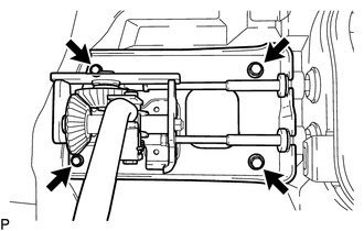
Remove the 4 bolts and remove the floor shift control shift lever retainer sub-assembly.
58701A
10.REMOVE FRONT ENGINE SERVICE COVER PANEL SUB-ASSEMBLY
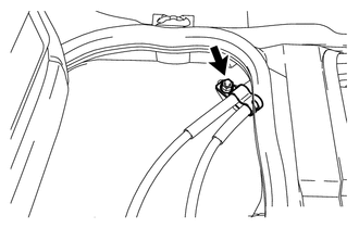
Remove the nut and disconnect the shift wire clamp from the front engine service cover panel sub-assembly.
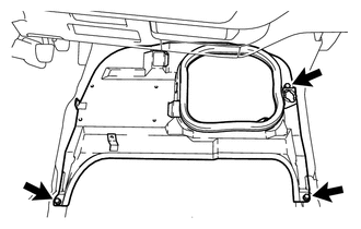
Remove the 3 bolts and remove the front engine service cover panel sub-assembly.
88310A
11.REMOVE NO. 1 V (COOLER COMPRESSOR TO CRANKSHAFT PULLEY) BELT (w/ Air Conditioning System)
16361A
12.REMOVE FAN AND GENERATOR V BELT
27020
13.REMOVE GENERATOR ASSEMBLY
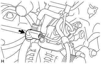
Remove the terminal cap.
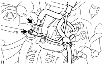
Remove the nut and disconnect the terminal B.
Disconnect the connector and detach the clamp.
| *a | Nut |
| *b | Connector |
| *c | Clamp |
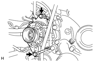
Remove the 2 bolts and generator assembly.
Remove the bolt and wiring harness bracket from the generator assembly.