METER / GAUGE / DISPLAY METER / GAUGE SYSTEM Fuel Receiver Gauge Malfunction
DESCRIPTION
The combination meter assembly controls the fuel receiver gauge in accordance with the resistance of the fuel sender gauge, which varies depending on the amount of fuel remaining in the fuel tank.
WIRING DIAGRAM
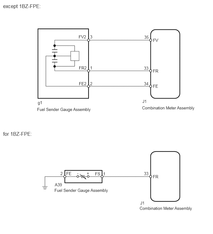
CAUTION / NOTICE / HINT
- NOTICE:
-
When replacing the combination meter assembly, always replace it with a new one. If a combination meter assembly which was installed to another vehicle used, the information stored in it will not match the information from the vehicle and a DTC may be stored.
PROCEDURE
- Result:
Engine model Proceed to except 1BZ-FPE A for 1BZ-FPE B
A
B
Using the GTS, perform the Active Test (Click hereVehicle Interior>METER / GAUGE / DISPLAY>METER / GAUGE SYSTEM>DATA LIST / ACTIVE TEST).
| Tester Display | Test Part | Control Range | Diagnostic Note |
|---|---|---|---|
| Fuel Meter Operation | Fuel receiver gauge assembly | OFF, Sender E, Empty, Warning, 1/4, 1/2, 3/4, Full or Sender F | - |
- OK:
Fuel receiver gauge assembly indication is normal according to the GTS operation.
- Result:
Proceed to OK NG
OK
NG
Using the GTS, read the Data List (Click hereVehicle Interior>METER / GAUGE / DISPLAY>METER / GAUGE SYSTEM>DATA LIST / ACTIVE TEST).
| Tester Display | Measurement Item / Range | Normal Condition | Diagnostic Note |
|---|---|---|---|
| Fuel Input | Fuel input / Min.: 0, Max.: 127.5 | Current fuel level displayed | Unit: Liter |
- OK:
Fuel level data displayed on the GTS is almost the same as the fuel receiver gauge assembly indication.
- Result:
Proceed to OK NG
OK
NG
Remove the fuel sender gauge assembly.
Inspect the fuel sender gauge assembly.
- Result:
Proceed to OK NG
OK
NG
Disconnect the J1 combination meter assembly connector.
Disconnect the g1 fuel sender gauge assembly connector.
Measure the resistance according to the value(s) in the table below.
- Standard Resistance:
Tester Connection Condition Specified Condition J1-35 (FV) - g1-3 (FV2) Always Below 1 Ω J1-34 (FE) - g1-2 (FE2) Always Below 1 Ω J1-33 (FR) - g1-1 (FR2) Always Below 1 Ω J1-35 (FV) - Body ground Always 10 kΩ or higher J1-34 (FE) - Body ground Always 10 kΩ or higher J1-33 (FR) - Body ground Always 10 kΩ or higher
- Result:
Proceed to OK NG
OK
NG
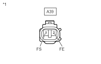
Disconnect the fuel sender gauge assembly connector.
Turn the ignition switch to ON, and then check the position of the receiver gauge needle.
- OK:
Needle position is on EMPTY.
| *1 | Front view of wire harness connector
(to Fuel Sender Gauge) |
Connect terminals 1 and 2 on the wire harness side connector of the fuel sender gauge.
Turn the ignition switch to ON, and then check the position of the receiver gauge needle.
- OK:
Needle position is on FULL.
- Result:
Proceed to OK NG
OK
NG
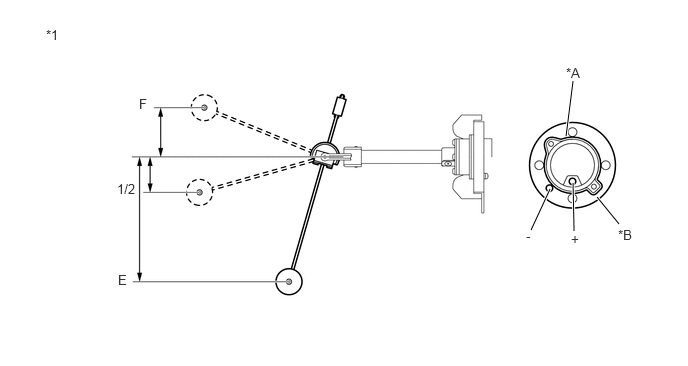
| *1 | Component without harness connected
(Fuel Sender Gauge Assembly) |
*A | LPG Tank Fuel Sender Gauge Sub-assembly |
| *B | Fuel Sender Gauge Body Sub-assembly | - | - |
Remove the fuel sender gauge assembly.
Check that the float moves smoothly between E and F.
Measure the resistance according to the value(s) in the table below.
- Standard Resistance:
Tester Connection Float Level Float Position (mm (in.)) Specified Condition Fuel Sender (+) - Fuel Sender (-) F 53.8 to 55.4 (2.11 to 2.18) 0.9 to 5.1 Ω 1/2 40.6 (1.59) 27.7 to 37.3 Ω E 134.9 to 142.7 (5.50 to 5.61) 102.3 to 117.7 Ω
- Result:
Proceed to OK NG
OK
NG
Replace the LPG tank fuel sender gauge sub-assembly.
- Result:
Proceed to NEXT
NEXT
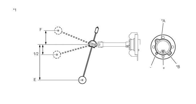
| *1 | Component without harness connected
(Fuel Sender Gauge Assembly) |
*A | LPG Tank Fuel Sender Gauge Sub-assembly |
| *B | Fuel Sender Gauge Body Sub-assembly | - | - |
Remove the fuel sender gauge assembly.
Check that the float moves smoothly between E and F.
Measure the resistance according to the value(s) in the table below.
- Standard Resistance:
Tester Connection Float Level Float Position (mm (in.)) Specified Condition Fuel Sender (+) - Fuel Sender (-) F 53.8 to 55.4 (2.11 to 2.18) 0.9 to 5.1 Ω 1/2 40.6 (1.59) 27.7 to 37.3 Ω E 134.9 to 142.7 (5.50 to 5.61) 102.3 to 117.7 Ω
- Result:
Proceed to OK NG
OK
NG
Disconnect the J1 combination meter assembly connector.
Disconnect the A39 fuel sender gauge assembly connector.
Measure the resistance according to the value (s) in the table below.
- Standard Resistance:
Tester Connection Condition Specified Condition J1-33 (FR) - A39-1 (FS) Always Below 1 Ω A39-2 (FE) - Body ground Always Below 1 Ω J1-33 (FR) - Body ground Always 10 kΩ or higher
- Result:
Proceed to OK NG
OK
NG
Disconnect the A39 fuel sender gauge assembly connector.
Measure the resistance according to the value (s) in the table below.
- Standard Resistance:
Tester Connection Condition Specified Condition A39-1 (FS) - fuel sender (+) Always Below 1 Ω A39-2 (FE) - fuel sender (-) Always Below 1 Ω A39-1 (FS) - Body ground Always 10 kΩ or higher
- Result:
Proceed to OK NG
OK
NG