FRONT SUSPENSION FRONT STABILIZER BAR INSTALLATION
PROCEDURE

 48815
1.INSTALL FRONT NO. 1 STABILIZER BAR BUSH
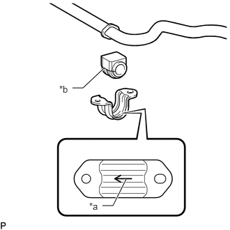
Install the 2 rear stabilizer bushes so that the slit is facing the front of the vehicle.
| *a | Arrow |
| *b | Slit |
Install the 2 rear stabilizer bracket covers so that the arrow is facing the front of the vehicle.
48811
2. TEMPORARILY INSTALL FRONT STABILIZER BAR
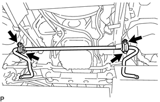
Temporarily install the front stabilizer bar with the 4 bolts.
48810
3.INSTALL FRONT STABILIZER LINK ASSEMBLY LH
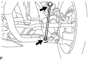
Install the front stabilizer link assembly LH with the 2 nuts.
- Torque:
74 N*m (755 kgf*cm, 55 ft.*lbf)
- HINT:
-
If the ball joint turns together with the nut, use a 6 mm hexagon wrench to hold the stud in place.
48820B
4.INSTALL FRONT STABILIZER LINK ASSEMBLY RH
- HINT:
-
Use the same procedures described for the LH side.
5. TIGHTEN FRONT STABILIZER BAR
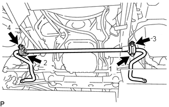
Tighten the 4 bolts in the order shown in the illustration.
- Torque:
45 N*m (459 kgf*cm, 33 ft.*lbf)
6.INSTALL NO. 1 ENGINE UNDER COVER (for Plastic Type)
7.INSTALL FRONT WHEEL