14B FUEL FUEL INJECTION PUMP INJECTION PUMP DISASSEMBLY
CAUTION / NOTICE / HINT
- NOTICE:
- w/ HAC and 15B-FT
-
When re-using the governor cover assembly, to prevent oil spilling out from the bushing of the governor cover when doing steps 1 to 13, remove it wlthou1 tilting it 45° or more from the horizontal.
PROCEDURE

 1. MOUNT PUMP ASSEMBLY TO SST (STAND)
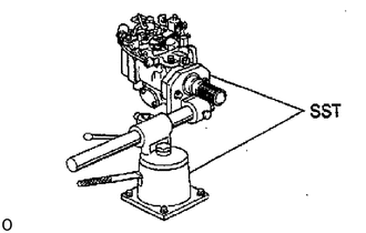
- SST
- 09241-76022
09245-54010
2.REMOVE SPLINE SHAFT
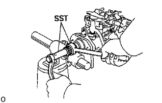
Using SST, remove the round nut.
- SST
- 09260-58010 (09266-76011)
09278-46020
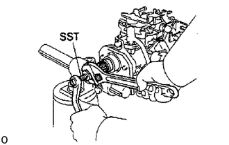
Using SST, remove the spline shaft.
- SST
- 09260-58010 (09267-76011)
3.REMOVE SET KEY OF SPLINE SHAFT FROM DRIVE SHAFT
4.REMOVE FUEL PIPES
5.REMOVE CLAMP FOR FUEL INLET PIPE (BU)
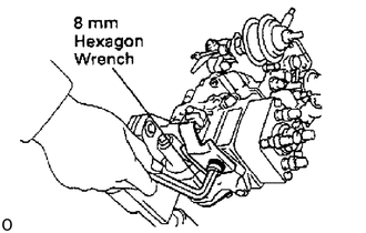
Using an 8 mm hexagon wrench, remove the bolt, plate washer and clamp.
6.REMOVE IDLE-UP LEVER
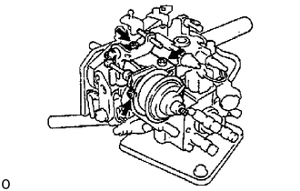
Set the adjusting lever to maximum position.
Using a 5 mm hexagon wrench, remove the 3 bolts, the idle-up actuator, lever assembly and collar.
7.REMOVE THERMO WAX
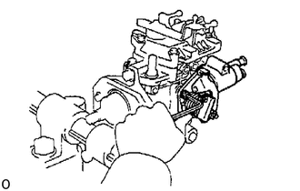
Remove the 2 bolts, thermo wax and O-ring.
8.REMOVE DASH POT
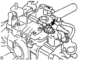
Remove the dash pot and gasket.
9.REMOVE FUEL CUT SOLENOID
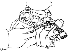
Disconnect the lead wire connector from the bracket.
Disconnect the dust cover from the fuel cut solenoid.
Remove the nut, lead wire and dust cover.
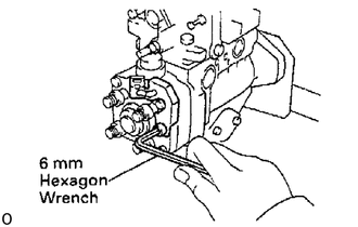
Using a 6 mm hexagon wrench, remove the bolt and connector bracket.
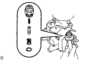
Remove the fuel cut solenoid, O-ring, spring, valve, strainer and wave washer.
10.REMOVE PICKUP SENSOR
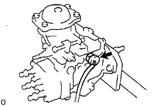
Remove the pickup sensor and O-ring.
Disconnect the sensor lead wires from the connector.
11.REMOVE ADJUSTING LEVER
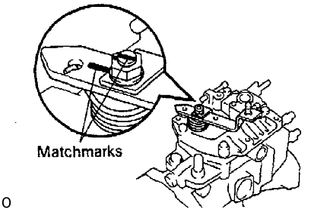
Place the matchmarks on the adjusting lever and shaft.
15B-FT:
Remove the nut, return spring guide, adjusting lever and 2 return springs.
Others:
Remove the nut, adjusting lever and adjusting spring.
12.REMOVE GOVERNOR COVER
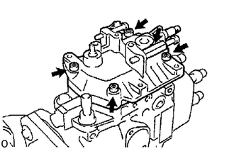
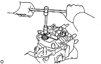
Remove the idle speed adjusting screw.
Using a 5 mm hexagon wrench. remove the 4 bolts.
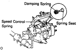
Disconnect the speed control spring from the spring seat, and remove the spring seat, damper spring, speed control spring, the governor cover, adjusting shaft assembly and gasket.
- NOTICE:
- w/ HAC and 15B-FT
-
After removing the governor cover assembly, do not place it at an angle 45° or more from the horizontal.
13.REMOVE GOVERNOR ADJUSTING LEVER SHAFT FROM GOVERNOR COVER
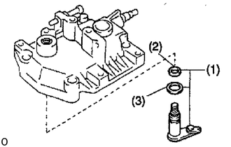
Remove the following parts from the governor cover:
Adjusting lever shaft, O-ring and washer assembly
O-ring
Washer
14.DISASSEMBLE HIGH ALTITUDE COMPENSATOR (w/ HAC) OR BOOST COMPENSATOR (15B-FT)
Remove lever control spring
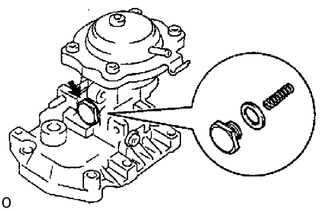
Remove the bolt, gasket and lever control spring.
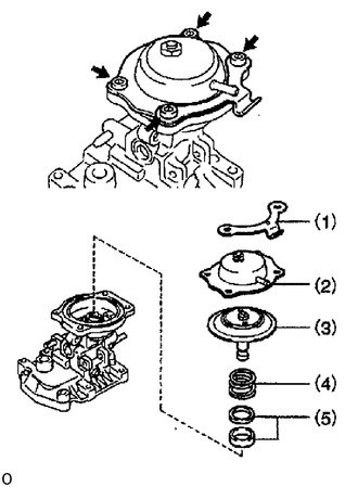
15B-FT: Remove boost compensator diaphragm
Using a 5 mm hexagon wrench, remove the 4 bolts and these parts:
Fuel outlet pipe clamp
Diaphragm cover
Diaphragm assembly
Spring
Shim(s)
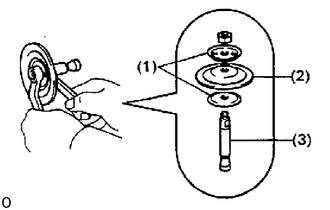
15B-FT: Remove boost compensator diaphragm
Remove the nut, and disassemble the following parts:
2 spring seats
Diaphragm
Push rod
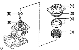
w/ HAC: Remove pneumatic bellows
Using a 5 mm hexagon wrench, remove the 4 bolts and these parts:
Pneumatic bellows cover
Gasket
Pneumatic bellows
2 rubber caps
Push rod
Pneumatic bellows spring
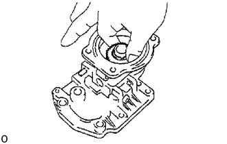
15B-FT:
Remove guide bushing
Remove control lever
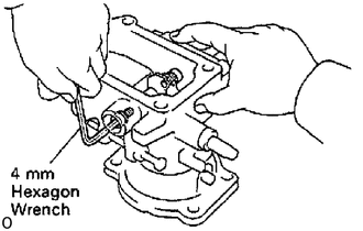
Using a 4 mm hexagon wrench, remove the 2 bolts and gaskets.
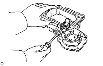
Using a small screwdriver, push out the support pin and remove the control lever.
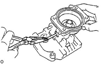
Using needle nose pliers, remove the connecting pin.
- NOTICE:
-
Be careful not to damage the connecting pin.
-
Tape the tip of the pliers.
Remove overflow screw
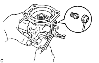
Remove the rubber cap and overflow screw.
15.CHECK FLYWEIGHT HOLDER THRUST CLEARANCE
Click hereEngine / Hybrid System>14B (FUEL)>FUEL INJECTION PUMP>INJECTION PUMP ASSEMBLY
- Thrust clearance:
0.15 - 0.35 mm (0.0059 - 0.0138 in.)
16.REMOVE GOVERNOR SHAFT AND FLYWEIGHT HOLDER
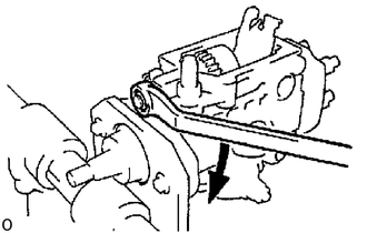
Remove the governor shaft lock nut by turning it clockwise.
- NOTICE:
-
The governor shaft and lock nut have LH threads.
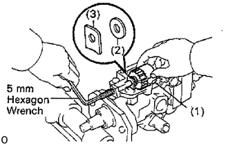
Using a 5 mm hexagon wrench, remove the governor shaft clockwise, and remove the following parts:
- HINT:
-
Be careful not to drop the 2 washers into the pump housing.
Flyweight holder assembly
No.1 flyweight washer
Governor gear adjusting washer
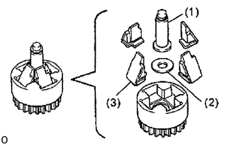
Remove the following parts from the flyweight holder.
Governor sleeve
No.2 flyweight washer
4 flyweights
17.REMOVE DISTRIBUTIVE HEAD PLUG
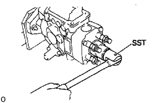
Using SST, remove the distributive head plug.
- SST
- 09260-54012 (09262-54010)
18.REMOVE DELIVERY VALVE HOLDERS (w/o CPV)
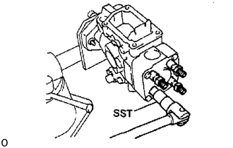
Using SST, remove the 4 delivery valve holders and springs.
- SST
- 09260-54012 (09269-54020)
Remove the 4 delivery valves and gaskets.
- NOTICE:
-
Do not touch the sliding surfaces of the delivery valve with your hand.
- HINT:
-
Arrange the delivery valves, springs, and holders in order.
19.REMOVE DISTRIBUTIVE HEAD
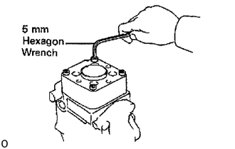
Using a 5 mm hexagon wrench, remove the 4 bolts.
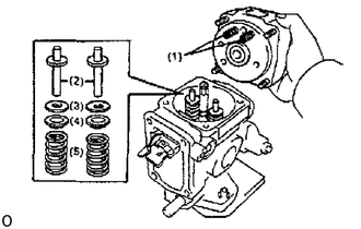
Remove the distributive head and following parts:
2 lever support springs
2 plunger spring guides
2 plunger spring shims
2 upper spring seats
2 plunger springs
20.REMOVE PUMP PLUNGER
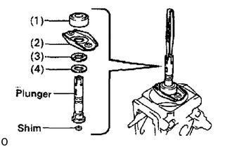
Using SST, remove the pump plunger and plunger adjusting shim together with the following parts:
- SST
- 09260-54012 (09269-54030)
- NOTICE:
-
Do not touch the sliding surfaces of the pump plunger with your hand.
Spill ring
Lower spring seat
Upper plunger plate
Lower plunger plate
21.REMOVE GOVERNOR LINK
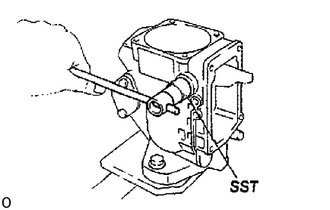
Using SST, remove the 2 support bolts, gaskets and governor link.
- SST
- 09260-54012
09269-54040
22.REMOVE FACE CAMPLATE AND COUPLING
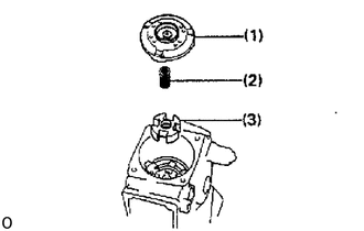
Remove these parts:
Face camplate
3B, 14B:
Coupling spring
Coupling
23.REMOVE ROLLER RING AND DRIVE SHAFT
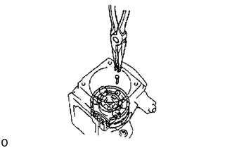
Remove the timer clip and stopper pin.
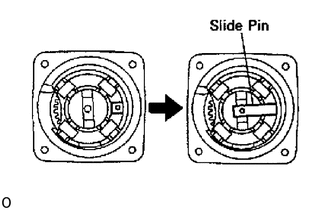
Push the slide pin toward inside.
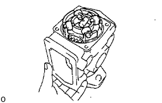
Push the drive shaft, and remove the roller ring, 4 rollers and shims assembly.
- NOTICE:
- ·
Be careful not to drop the rollers.
·Do not alter the position or assembly of the rollers.
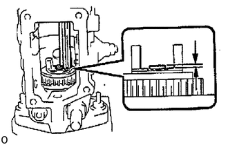
15B-F, 15B-FT:
Using vernier calipers, measure the protrusion of the coupling spring.
- Protrusion:
1.0 - 1.6 mm (0.039 - 0.063 in.)
If the protrusion is not as specified, replace the coupling spring.
- NOTICE:
-
Do not remove the coupling spring unless necessary. If you remove the coupling spring, replace it with a new one.
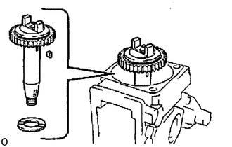
Remove the drive shaft, governor drive gear, 2 joint rubbers assembly, set key and drive shaft washer.
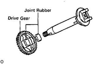
Remove the drive gear and 2 joint rubbers from the drive shaft.
24.REMOVE TIMER
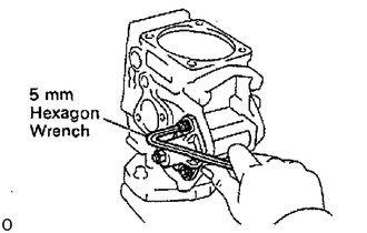
Using a 5 mm hexagon wrench, remove the 2 LH timer cover bolts.
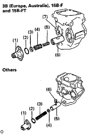
Remove these parts:
3B (Europe, Australia), 15B-F and 16B-FT:
LH timer cover, timer adjusting screw and nut assembly
O-ring
Shim
Outer spring
Inner spring
Piston
Sub-piston
Remove these parts:
Others:
LH timer cover, timer adjusting screw and nut assembly
O-ring
Spring
Timer washer
Piston
Sub-piston
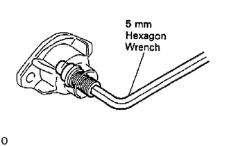
Remove the nut from the LH timer cover.
Using a 5 mm hexagon wrench, remove the timer adjusting screw.
Remove the O-ring from the timer adjusting ring.
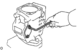
Using a 5 mm hexagon wrench, remove the 2 bolts, RH timer cover and O-ring.
25.REMOVE FUEL FEED PUMP
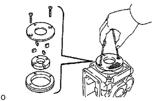
Remove the 2 screws.
Using a piece of wire, remove the feed pump cover.
Remove the feed pump rotor, 4 blades and liner.
- NOTICE:
- ·
Be careful not to interchange the blade positions.
·Be careful not to damage the pump body.
26.REMOVE REGULATOR VALVE
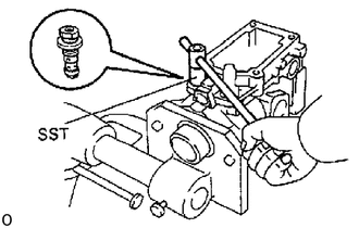
Using SST, remove the regulator valve and 2 O-rings.
- SST
- 09260-54012 (09262-54020)
27.REMOVE FUEL INLET HOLLOW SCREW
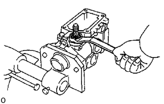
Remove the hollow screw and gasket.