ALIGNMENT / HANDLING DIAGNOSIS FRONT WHEEL ALIGNMENT(for 1HZ) ADJUSTMENT
PROCEDURE

 1.INSPECT TIRES
2.MEASURE VEHICLE HEIGHT
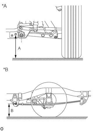
Bounce the vehicle up and down at the corners to stabilize the suspension and measure the vehicle height.
- Measuring points:
- Front Side A:
Ground clearance of lower arm front side cam bolt front center
- Rear Side B:
Ground clearance of rear leaf spring front side bolt center
| *A | for Front Side |
| *B | for Rear Side |
- Standard Vehicle Height (Unloaded Vehicle):
Vehicle Model Tire Size Front Side A Spring Type Rear Side B
(Reference)HZB70L-ZGMRS 215/70R17.5 278 mm
(10.94 in.)2-Leaf Spring 337 mm
(13.27 in.)8-Leaf Spring 333 mm
(13.11 in.)7.00R16 296 mm
(11.65 in.)2-Leaf Spring 352 mm
(13.86 in.)8-Leaf Spring 348 mm
(13.70 in.)HZB70L-ZGMSS 215/70R17.5 278 mm
(10.94 in.)2-Leaf Spring 336 mm
(13.23 in.)8-Leaf Spring 332 mm
(13.07 in.)7.00R16 292 mm
(11.50 in.)2-Leaf Spring 350 mm
(13.78 in.)8-Leaf Spring 346 mm
(13.62 in.)HZB70L-ZGMSSV 215/70R17.5 273 mm
(10.75 in.)2-Leaf Spring 338 mm
(13.31 in.)8-Leaf Spring 334 mm
(13.15 in.)HZB70L-ZXMSS 215/70R17.5 278 mm
(10.94 in.)2-Leaf Spring 338 mm
(13.31 in.)8-Leaf Spring 334 mm
(13.15 in.)7.00R16 292 mm
(11.50 in.)2-Leaf Spring 352 mm
(13.86 in.)8-Leaf Spring 348 mm
(13.70 in.)HZB70L-ZXMSSV 215/70R17.5 273 mm
(10.75 in.)2-Leaf Spring 339 mm
(13.35 in.)8-Leaf Spring 335 mm
(13.19 in.)HZB70R-ZGMSS 215/70R17.5 278 mm
(10.94 in.)2-Leaf Spring 337 mm
(13.27 in.)8-Leaf Spring 333 mm
(13.11 in.)7.00R16 292 mm
(11.50 in.)2-Leaf Spring 351 mm
(13.82 in.)8-Leaf Spring 347 mm
(13.66 in.)HZB70R-ZGMNS 215/70R17.5 278 mm
(10.94 in.)2-Leaf Spring 335 mm
(13.19 in.)8-Leaf Spring 331 mm
(13.03 in.)7.00R16 292 mm
(11.50 in.)2-Leaf Spring 349 mm
(13.74 in.)8-Leaf Spring 346 mm
(13.62 in.)HZB70L-ZGMNS 215/70R17.5 273 mm
(10.75 in.)2-Leaf Spring 332 mm
(13.03 in.)8-Leaf Spring 328 mm
(12.91 in.)7.00R16 292 mm
(11.50 in.)2-Leaf Spring 347 mm
(13.66 in.)8-Leaf Spring 343 mm
(13.50 in.)HZB70L-ZGMTS 215/70R17.5 278 mm
(10.94 in.)2-Leaf Spring 334 mm
(13.15 in.)8-Leaf Spring 331 mm
(13.03 in.)7.00R16 292 mm
(11.50 in.)2-Leaf Spring 348 mm
(13.70 in.)8-Leaf Spring 345 mm
(13.58 in.)HZB70L-ZGMNSV 215/70R17.5 273 mm
(10.75 in.)2-Leaf Spring 334 mm
(13.15 in.)8-Leaf Spring 330 mm
(12.99 in.)
- NOTICE:
-
Before inspecting the wheel alignment, check the vehicle height.
3. INSPECT CAMBER, CASTER AND STEERING AXIS INCLINATION
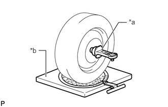
Install a camber-caster-kingpin gauge and place the front wheels on the center of a turning radius gauge.
| *a | Camber-caster-kingpin Gauge |
| *b | Turning Radius Gauge |
w/ Wheel Cap:
Remove the wheel cap.
Remove the front axle hub grease cap.
Click hereDrivetrain>AXLE AND DIFFERENTIAL>FRONT AXLE HUB>REMOVAL
Remove the cotter pin and lock cap.
Align the end of the camber-caster-kingpin gauge center rod to the middle of the spindle and install the front axle hub to the camber-caster-kingpin gauge.
- NOTICE:
-
Take care not to apply grease to the camber-caster-kingpin gauge.
Inspect the camber, caster and steering axis inclination.
- Camber, caster and steering axis inclination (Unloaded Vehicle):
Camber Caster Steering Axis Inclination
(Reference)0°00' +/- 30'
(0.0° +/- 0.5°)4°30' +/- 30'
(4.5° +/- 0.5°)13°00'
(13.0°)
- NOTICE:
- ·
Perform the inspection while the vehicle is empty.
·The tolerance for the difference between the left and right wheels is 30' (0.5°) or less for both the camber and caster.
·Remove any garbage and foreign matter from the end of the axle hub before checking.
If the camber and caster are not as specified, adjust them.
If the steering axis inclination is not as specified after the camber and caster have been correctly adjusted, recheck the steering knuckle and front wheel for distortion and slack.
Remove the camber-caster-kingpin gauge.
Install the lock cap and a new cotter pin.
Install the front axle hub grease cap.
w/ Wheel Cap:
Install the wheel cap.
4.ADJUST CAMBER AND CASTER
- NOTICE:
-
Inspect the toe-in after the camber and caster have been adjusted.
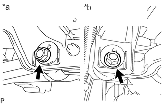
Loosen the front and/or rear nut.
| *a | Front Side |
| *b | Rear Side |
Turn the front camber adjust cam and adjust the camber.
- Camber:
0°00' +/- 30' (0.0° +/- 0.5°)
Turn the rear camber adjust cam and adjust the caster.
- Caster:
4°30' +/- 30' (4.5° +/- 0.5°)
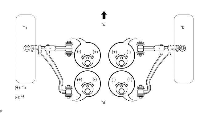
| *a | LH | *b | RH |
| *c | Front Camber Adjust Cam | *d | Rear Camber Adjust Cam |
| *e | Shorter | *f | Longer |

|
Front of the Vehicle | - | - |
- NOTICE:
- ·
Perform the inspection while the vehicle is empty.
·The tolerance for the difference between the left and right wheels is 30' (0.5°) or less for both the camber and caster.
·Make sure to check the caster and toe-in after adjusting the camber.
·Make sure to check the toe-in after adjusting the caster.
·Try to adjust the camber and caster to the central values.
- HINT:
- ·
The camber and caster changes by approximately +/- 10' when the front camber adjust cam is rotated by +/-1 gauge marks (+/- 1.0 mm).
·The caster changes by approximately +/- 10' but the camber remains mostly unchanged when the rear camber adjust cam is rotated by +/-1 gauge marks (+/- 1.0 mm).
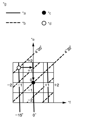
How to read the adjustment chart (using examples).
| *a | Camber |
| *b | Caster |
| *c | Standard Value |
| *d | Measured Value |
| *e | Rear Cam Graduation |
| *f | Front Cam Graduation |
| *g | Example |
Find the wheel alignment standard value applicable for a particular model.
Mark the selected standard value on the adjustment chart.
- Camber:
0°00' (0°)
- Caster:
4°30' (4.50°)
Mark the alignment value measured on the adjustment chart when the vehicle was noloaded.
- Example:
- Camber:
-0°15' (-0.25°)
- Caster:
4°00' (4.0°)
As shown in the chart, read the distance between the standard value and measured value, and then adjust the front and/or rear adjusting cam accordingly.
- Front camber adjust cam:
+ (Shorter) 1.4
- Rear camber adjust cam:
- (Longer) 1.5
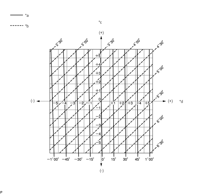
| *a | Camber | *b | Caster |
| *c | Rear Cam Graduation | *d | Front Cam Graduation |
Tighten the front and/or rear nut.
| *a | Front Side |
| *b | Rear Side |
- Torque:
215 N*m (2192 kgf*cm, 159 ft.*lbf)
5.INSPECT TOE-IN
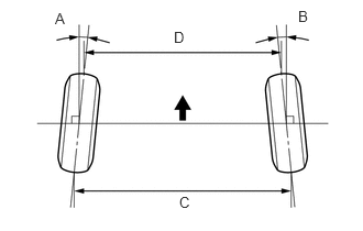
Bounce the vehicle up and down at the corners to stabilize the suspension and inspect toe-in.
- Toe-in (Unloaded Vehicle):
Tire Size A + B C - D 215/70R17.5 0°12' +/-5'
(0.20° +/-0.08°)2.5 +/- 1.0 mm
(0.0984 +/- 0.0394 in.)7.00R16 0°16' +/-4'
(0.26° +/-0.07°)3.5 +/- 1.0 mm
(0.138 +/- 0.0394 in.)
|
|
Front of the Vehicle |
If the toe-in is not within the specified range, adjust it at the rack ends.
6.ADJUST TOE-IN
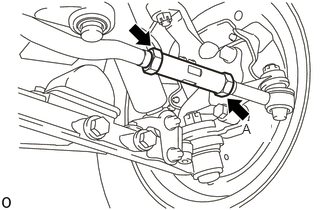
Loosen the 2 nuts.
- NOTICE:
-
Nut A is a left-hand thread nut. Therefore, make sure to install in the correct direction.
Adjust the toe-in by turning the left and right tie rod tubes equally.
- Toe-in (Unloaded Vehicle):
Tire Size A + B C - D 215/70R17.5 0°12' +/-5'
(0.20° +/-0.08°)2.5 +/- 1.0 mm
(0.0984 +/- 0.0394 in.)7.00R16 0°16' +/-4'
(0.26° +/-0.07°)3.5 +/- 1.0 mm
(0.138 +/- 0.0394 in.)
- NOTICE:
-
Nut A is a left-hand thread nut. Therefore, make sure to install in the correct direction.
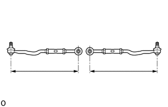
Measure the lengths of the right and left tie rod assembly.
- Standard:
- Right-left Difference:
2.0 mm (0.0787 in.) or less
Secure the tie rod tube width-across-flats and temporarily install the nuts on both sides.
Secure the tie rod tube width-across-flats and tighten the nuts on both sides.
- Torque:
70 N*m (714 kgf*cm, 52 ft.*lbf)
- NOTICE:
- ·
After adjusting the toe-in, check that the tolerance angle of the tie rod sub-assembly and No. 2 tie rod sub-assembly is 90°.
·After adjusting the toe-in, check that permissible swinging angle of the ball joint on both ends of the tie rod assembly is at the center.
7.INSPECT WHEEL TURNING ANGLE
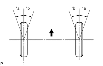
Turn the steering wheel fully, and measure the wheel turning angle.
- Wheel Turning Angle (Unloaded Vehicle):
Inside wheel Outside wheel
(Reference)39°30' +1°00'/-2°00'
(39.50°+1.00°/-2.00°)35°50'
(35.83°)
| *a | Inside |
| *b | Outside |
|
|
Front of the Vehicle |
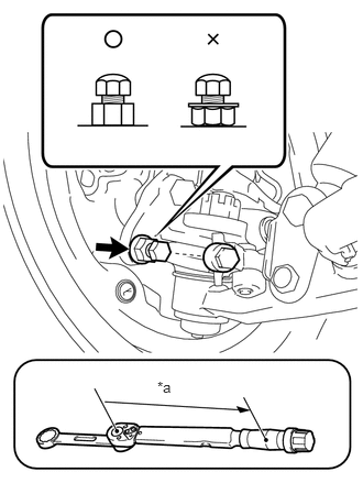
If the right and left wheel turning angles differ from the specified range, adjust the wheel turning angle with the knuckle stopper bolts.
Remove the knuckle stopper cover.
Secure the nut stopper bolt and loosen the lock nut.
Adjust the knuckle stopper bolt length.
Secure the nut stopper bolt and tighten the lock nut.
- Torque:
- Specified tightening torque : 49 N*m (500 kgf*cm, 36 ft.*lbf)
- NOTICE:
-
Be sure to install the nut in the correct direction.
- HINT:
- ·
Calculate the torque wrench reading when changing the fulcrum length of the torque wrench.
Click hereGeneral>INTRODUCTION>REPAIR INSTRUCTION>PRECAUTION
·When using a ball joint lock nut wrench (fulcrum length of 150 mm (5.906 in.)) + torque wrench (fulcrum length of 255 mm (10.039 in.)): 30.9 N*m (315 kgf*cm, 23 ft.*lbf)
Install a new knuckle stopper cover.
8.ADJUST CENTER ARM STOPPER
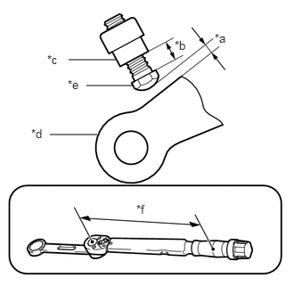
Adjust so that the dimension between the center arm and center arm stopper bolt is as shown when the tire turning angle on the inner side is 39°30'.
| *a | 2.0 mm (0.079 in.) or more |
| *b | 12.0 to 15.0 mm (0.473 to 0.590 in.) |
| *c | Nut |
| *d | Center Arm |
| *e | Center Arm Stopper bolt |
| *f | Torque Wrench Fulcrum Length |
While securing the center arm stopper bolt, tighten the nut.
- Torque:
- Specified tightening torque : 49 N*m (500 kgf*cm, 36 ft.*lbf)
- HINT:
- ·
Calculate the torque wrench reading when changing the fulcrum length of the torque wrench.
Click hereGeneral>INTRODUCTION>REPAIR INSTRUCTION>PRECAUTION
·When using a ball joint lock nut wrench (fulcrum length of 150 mm (5.906 in.)) + torque wrench (fulcrum length of 255 mm (10.039 in.)): 30.9 N*m (315 kgf*cm, 23 ft.*lbf)
9.ADJUST PITMAN ARM STOPPER
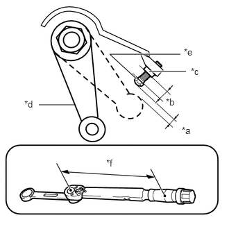
Adjust so that the dimension between the pitman arm and pitman arm stopper bolt is as shown when the tire turning angle on the inner side is 39°30'.
| *a | 2.0 mm (0.079 in.) or more |
| *b | 12.0 to 15.0 mm (0.473 to 0.590 in.) |
| *c | Nut |
| *d | Pitman Arm |
| *e | Pitman Arm Stopper bolt |
| *f | Torque Wrench Fulcrum Length |
While securing the pitman arm stopper bolt, tighten the nut.
- Torque:
- Specified tightening torque : 49 N*m (500 kgf*cm, 36 ft.*lbf)
- HINT:
- ·
Calculate the torque wrench reading when changing the fulcrum length of the torque wrench.
Click hereGeneral>INTRODUCTION>REPAIR INSTRUCTION>PRECAUTION
·When using a ball joint lock nut wrench (fulcrum length of 150 mm (5.906 in.)) + torque wrench (fulcrum length of 255 mm (10.039 in.)): 30.9 N*m (315 kgf*cm, 23 ft.*lbf)