Home › Engine / Hybrid System › N04C-WA (EMISSION CONTROL) › UREA SELECTIVE CATALYTIC REDUCTION SYSTEM › from 2019.08
RM2850E _51 Engine / Hybrid System _082614 N04C-WA EMISSION CONTROL _0400651 UREA SELECTIVE CATALYTIC REDUCTION SYSTEM J

N04C-WA EMISSION CONTROL  UREA SELECTIVE CATALYTIC REDUCTION SYSTEM  ECU Power Source Circuit  


DESCRIPTION

When the ignition switch is turned to ON, battery power is supplied to the IGSW terminal of the DCU (emission control ECU assembly) and RLY1 is operated.

As a result, the ABS MTR/DCU relay contact closes and power is supplied to the +BU terminals of the DCU (emission control ECU assembly).

WIRING DIAGRAM
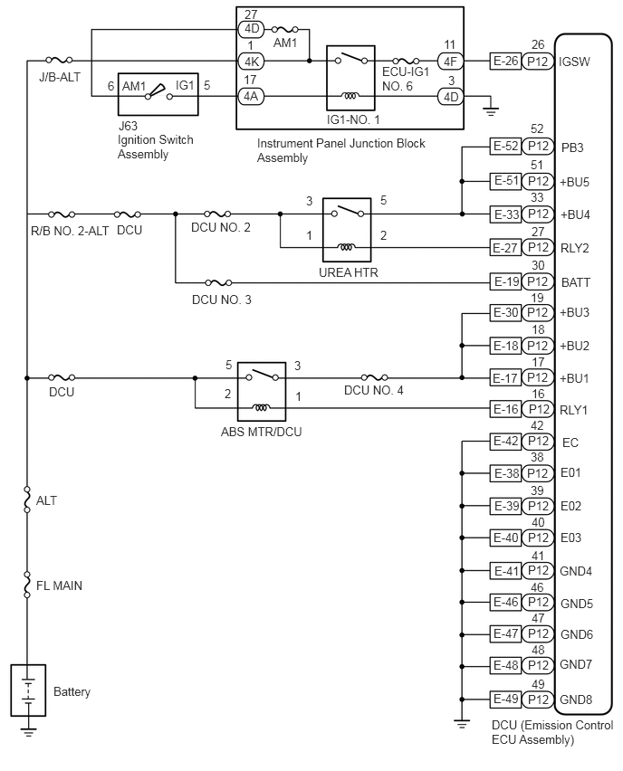
A444324E01
6.427,0.625 7.042,0.823 0.615,0.198 10 false IGSW 6.063,0.625 6.344,0.844 0.281,0.219 10 false P12 6.115,0.427 6.396,0.646 0.281,0.219 10 false 26 5.677,0.615 6.052,0.833 0.375,0.219 10 false E-26 4.396,0.74 4.958,1.104 0.563,0.365 10 false ECU-IG1 NO. 6 3.76,1.292 4.5,1.469 0.74,0.177 10 false IG1-NO. 1 1.354,1.521 2.292,1.927 0.938,0.406 10 false Ignition Switch Assembly 3.146,0.406 3.521,0.625 0.375,0.219 10 false AM1 0.448,0.802 1.292,1.021 0.844,0.219 10 false J/B-ALT 2.198,2.531 3.042,2.75 0.844,0.219 10 false DCU NO. 2 6.083,4.625 6.365,4.844 0.281,0.219 10 false P12 6.458,3.167 7.073,3.365 0.615,0.198 10 false BATT 5.677,3.51 6.052,3.729 0.375,0.219 10 false E-30 6.115,2.969 6.396,3.188 0.281,0.219 10 false 30 3.667,3.052 4.51,3.271 0.844,0.219 10 false UREA HTR 6.073,1.594 6.385,1.802 0.313,0.208 10 false P12 6.448,2.385 7.063,2.583 0.615,0.198 10 false +BU4 6.438,2.01 7.052,2.208 0.615,0.198 10 false +BU5 5.688,2.385 6.063,2.604 0.375,0.219 10 false E-33 6.104,2.188 6.385,2.406 0.281,0.219 10 false 33 6.073,2 6.385,2.219 0.313,0.219 10 false P12 6.104,1.813 6.385,2.031 0.281,0.219 10 false 51 5.688,1.99 6.063,2.208 0.375,0.219 10 false E-51 6.458,1.615 7.073,1.813 0.615,0.198 10 false PB3 6.073,2.375 6.427,2.594 0.354,0.219 10 false P12 5.677,1.594 6.052,1.813 0.375,0.219 10 false E-52 6.104,1.396 6.385,1.615 0.281,0.219 10 false 52 6.448,2.771 7.063,2.969 0.615,0.198 10 false RLY2 6.073,2.76 6.406,2.979 0.333,0.219 10 false P12 5.667,2.771 6.042,2.99 0.375,0.219 10 false E-27 6.115,2.583 6.396,2.802 0.281,0.219 10 false 27 6.438,3.51 7.052,3.708 0.615,0.198 10 false +BU3 6.063,3.156 6.396,3.375 0.333,0.219 10 false P12 6.104,3.344 6.385,3.563 0.281,0.219 10 false 19 5.688,3.156 6.063,3.375 0.375,0.219 10 false E-19 6.438,3.896 7.052,4.094 0.615,0.198 10 false +BU2 6.063,3.51 6.396,3.74 0.333,0.229 10 false P12 6.115,3.708 6.396,3.927 0.281,0.219 10 false 18 5.677,3.896 6.052,4.115 0.375,0.219 10 false E-18 6.438,4.271 7.052,4.469 0.615,0.198 10 false +BU1 6.063,3.896 6.344,4.115 0.281,0.219 10 false P12 6.115,4.083 6.396,4.302 0.281,0.219 10 false 17 5.667,4.271 6.042,4.49 0.375,0.219 10 false E-17 6.063,4.26 6.406,4.469 0.344,0.208 10 false P12 6.115,4.448 6.396,4.667 0.281,0.219 10 false 16 5.677,4.625 6.052,4.844 0.375,0.219 10 false E-16 6.438,4.635 7.052,4.833 0.615,0.198 10 false RLY1 1.344,2.563 1.74,2.813 0.396,0.25 10 false DCU 2.542,4.885 3.646,5.135 1.104,0.25 10 false ABS MTR/DCU 0.417,5.677 0.823,5.896 0.406,0.219 10 false ALT 0.417,6.656 1.052,6.844 0.635,0.188 10 false FL MAIN 0.615,7.875 1.25,8.063 0.635,0.188 10 false Battery 6.073,4.99 6.406,5.208 0.333,0.219 10 false P12 6.063,5.365 6.344,5.583 0.281,0.219 10 false P12 6.073,5.74 6.385,5.958 0.313,0.219 10 false P12 6.073,6.104 6.375,6.323 0.302,0.219 10 false P12 6.073,6.479 6.354,6.698 0.281,0.219 10 false P12 6.073,6.844 6.417,7.083 0.344,0.24 10 false P12 6.073,7.208 6.448,7.417 0.375,0.208 10 false P12 6.073,7.573 6.385,7.792 0.313,0.219 10 false P12 6.073,7.969 6.385,8.188 0.313,0.219 10 false P12 6.448,5.354 6.729,5.573 0.281,0.219 10 false E01 6.448,5.74 6.729,5.958 0.281,0.219 10 false E02 6.448,6.104 6.729,6.323 0.281,0.219 10 false E03 6.469,5.01 6.75,5.229 0.281,0.219 10 false EC 6.438,6.49 6.896,6.667 0.458,0.177 10 false GND4 6.448,6.865 6.906,7.042 0.458,0.177 10 false GND5 6.448,7.219 6.906,7.396 0.458,0.177 10 false GND6 6.438,7.563 6.896,7.74 0.458,0.177 10 false GND7 6.438,7.969 6.896,8.146 0.458,0.177 10 false GND8 5.656,8.26 7.125,8.667 1.469,0.406 10 false DCU (Emission Control ECU Assembly) 5.677,4.99 6.052,5.208 0.375,0.219 10 false E-42 5.688,5.365 6.063,5.583 0.375,0.219 10 false E-38 5.688,5.74 6.063,5.958 0.375,0.219 10 false E-39 5.677,6.104 6.052,6.323 0.375,0.219 10 false E-40 5.677,6.844 6.052,7.063 0.375,0.219 10 false E-46 5.688,6.49 6.063,6.708 0.375,0.219 10 false E-41 5.677,7.208 6.052,7.427 0.375,0.219 10 false E-47 5.677,7.573 6.052,7.792 0.375,0.219 10 false E-48 5.677,7.958 6.052,8.177 0.375,0.219 10 false E-49 6.104,4.813 6.385,5.031 0.281,0.219 10 false 42 6.104,5.177 6.385,5.396 0.281,0.219 10 false 38 6.104,5.563 6.385,5.781 0.281,0.219 10 false 39 6.115,5.927 6.396,6.146 0.281,0.219 10 false 40 6.115,6.313 6.396,6.531 0.281,0.219 10 false 41 6.104,6.677 6.385,6.896 0.281,0.219 10 false 46 6.115,7.031 6.396,7.25 0.281,0.219 10 false 47 6.115,7.396 6.396,7.615 0.281,0.219 10 false 48 6.115,7.792 6.396,8.01 0.281,0.219 10 false 49 2.802,1.021 3.083,1.24 0.281,0.219 10 false 4A 5.104,1.031 5.385,1.25 0.281,0.219 10 false 4D 2.813,0.625 3.094,0.844 0.281,0.219 10 false 4K 5.104,0.625 5.385,0.844 0.281,0.219 10 false 4F 2.958,1.563 4.979,1.969 2.021,0.406 10 false Instrument Panel Junction Block Assembly 5.104,0.427 5.385,0.646 0.281,0.219 10 false 11 2.844,0.438 3.125,0.656 0.281,0.219 10 false 1 2.802,0.833 3.083,1.052 0.281,0.219 10 false 17 5.156,0.844 5.448,1.052 0.292,0.208 10 false 3 2.344,0.896 2.625,1.115 0.281,0.219 10 false 5 1.24,0.906 1.521,1.125 0.281,0.219 10 false 6 1.406,0.906 1.781,1.125 0.375,0.219 10 false AM1 2.021,0.896 2.396,1.115 0.375,0.219 10 false IG1 3.521,2.229 3.802,2.448 0.281,0.219 10 false 3 3.385,4.125 3.667,4.344 0.281,0.219 10 false 3 3.521,2.625 3.802,2.844 0.281,0.219 10 false 1 3.396,4.479 3.677,4.698 0.281,0.219 10 false 1 4.375,2.219 4.656,2.438 0.281,0.219 10 false 5 2.594,4.115 2.875,4.333 0.281,0.219 10 false 5 4.375,2.625 4.656,2.844 0.281,0.219 10 false 2 2.583,4.448 2.865,4.667 0.281,0.219 10 false 2 1.365,1.365 1.74,1.583 0.375,0.219 10 false J63 3.958,4.406 4.802,4.625 0.844,0.219 10 false DCU NO. 4 2.208,3.365 3.052,3.583 0.844,0.219 10 false DCU NO. 3 2.813,0.24 3.094,0.458 0.281,0.219 10 false 4D 2.813,0.083 3.094,0.302 0.281,0.219 10 false 27 0.563,4.427 0.958,4.677 0.396,0.25 10 false DCU 0.354,2.573 1.365,2.802 1.01,0.229 10 false R/B NO. 2-ALT

CAUTION / NOTICE / HINT

NOTICE:

Inspect the fuses of circuits related to this system before performing the following inspection procedure.


PROCEDURE
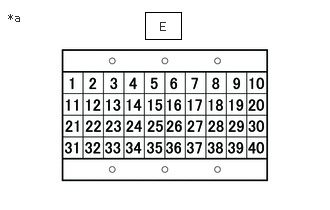
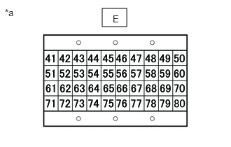
1.CHECK HARNESS AND CONNECTOR (DCU (EMISSION CONTROL ECU ASSEMBLY) - BODY GROUND)
a.
A405886C01
1.51,0.125 1.885,0.406 0.375,0.281 0.083,0.115 0.396,0.313 0.313,0.198 10 false *a 1.667,0.208 1.979,0.406 0.313,0.198 10 false E
*a Signal Check Harness No. 2 Lead Connector


A405887C01
1.521,0.125 1.885,0.396 0.365,0.271 0.073,0.104 0.385,0.302 0.313,0.198 10 false *a 1.677,0.198 1.833,0.396 0.156,0.198 10 false E
*a Signal Check Harness No. 2 Lead Connector


Connect the signal check harness No. 2 to the DCU (emission control ECU assembly) and DCU (emission control ECU assembly) vehicle side harness.


b.

Measure the resistance according to the value(s) in the table below.

Standard Resistance:
Tester Connection Condition Specified Condition
E-42 (EC) - Body ground Ignition switch off Below 1 Ω
E-38 (E01) - Body ground Ignition switch off Below 1 Ω
E-39 (E02) - Body ground Ignition switch off Below 1 Ω
E-40 (E03) - Body ground Ignition switch off Below 1 Ω
E-41 (GND4) - Body ground Ignition switch off Below 1 Ω
E-46 (GND5) - Body ground Ignition switch off Below 1 Ω
E-47 (GND6) - Body ground Ignition switch off Below 1 Ω
E-48 (GND7) - Body ground Ignition switch off Below 1 Ω
E-49 (GND8) - Body ground Ignition switch off Below 1 Ω


Result:
Proceed to
OK
NG


OK

2.INSPECT DCU (EMISSION CONTROL ECU ASSEMBLY) (+B VOLTAGE)

NG

REPAIR OR REPLACE HARNESS OR CONNECTOR

2.INSPECT DCU (EMISSION CONTROL ECU ASSEMBLY) (+B VOLTAGE)
a.
A405886C01
1.51,0.125 1.885,0.406 0.375,0.281 0.083,0.115 0.396,0.313 0.313,0.198 10 false *a 1.667,0.208 1.979,0.406 0.313,0.198 10 false E
*a Signal Check Harness No. 2 Lead Connector


Connect the signal check harness No. 2 to the DCU (emission control ECU assembly) and DCU (emission control ECU assembly) vehicle side harness.


b.

Turn the ignition switch to ON.


c.

Measure the voltage according to the value(s) in the table below.

Standard Voltage:
Tester Connection Condition Specified Condition
E-17 (+BU1) - E-38 (E01) Ignition switch ON 11 to 14 V
E-18 (+BU2) -E-38 (E01) Ignition switch ON 11 to 14 V
E-19 (+BU3) - E-38 (E01) Ignition switch ON 11 to 14 V


Result:
Proceed to
OK
NG


OK

3.INSPECT DCU (EMISSION CONTROL ECU ASSEMBLY) (+B VOLTAGE)

NG

9.INSPECT DCU (EMISSION CONTROL ECU ASSEMBLY) (IGSW VOLTAGE)
3.INSPECT DCU (EMISSION CONTROL ECU ASSEMBLY) (+B VOLTAGE)
a.
A405886C01
1.51,0.125 1.885,0.406 0.375,0.281 0.083,0.115 0.396,0.313 0.313,0.198 10 false *a 1.667,0.208 1.979,0.406 0.313,0.198 10 false E
*a Signal Check Harness No. 2 Lead Connector


A405887C01
1.521,0.125 1.885,0.396 0.365,0.271 0.073,0.104 0.385,0.302 0.313,0.198 10 false *a 1.677,0.198 1.833,0.396 0.156,0.198 10 false E
*a Signal Check Harness No. 2 Lead Connector


Connect the signal check harness No. 2 to the DCU (emission control ECU assembly) and DCU (emission control ECU assembly) vehicle side harness.


b.

Turn the ignition switch to ON.


c.

Measure the voltage according to the value(s) in the table below.

Standard Voltage:
Tester Connection Condition Specified Condition
E-33 (+BU4) - E-38 (E01) Ignition switch ON 11 to 14 V
E-51 (+BU5) -E-38 (E01) Ignition switch ON 11 to 14 V
E-52 (PB3) - E-38 (E01) Ignition switch ON 11 to 14 V


Result:
Proceed to
OK
NG


OK

NG

4.INSPECT DCU (EMISSION CONTROL ECU ASSEMBLY) (IGSW VOLTAGE)
a.
A405886C01
1.51,0.125 1.885,0.406 0.375,0.281 0.083,0.115 0.396,0.313 0.313,0.198 10 false *a 1.667,0.208 1.979,0.406 0.313,0.198 10 false E
*a Signal Check Harness No. 2 Lead Connector


Connect the signal check harness No. 2 to the DCU (emission control ECU assembly) and DCU (emission control ECU assembly) vehicle side harness.


b.

Turn the ignition switch to ON.


c.

Measure the voltage according to the value(s) in the table below.

Standard Voltage:
Tester Connection Switch Condition Specified Condition
E-26 (IGSW) - E-38 (E01) Ignition switch ON 11 to 14 V


Result:
Proceed to
OK
NG


OK

5.INSPECT DCU (EMISSION CONTROL ECU ASSEMBLY) (RLY2 VOLTAGE)

NG

12.INSPECT ABS MTR/DCU RELAY
5.INSPECT DCU (EMISSION CONTROL ECU ASSEMBLY) (RLY2 VOLTAGE)
a.
A405886C01
1.51,0.125 1.885,0.406 0.375,0.281 0.083,0.115 0.396,0.313 0.313,0.198 10 false *a 1.667,0.208 1.979,0.406 0.313,0.198 10 false E
*a Signal Check Harness No. 2 Lead Connector


Connect the signal check harness No. 2 to the DCU (emission control ECU assembly) and DCU (emission control ECU assembly) vehicle side harness.


b.

Turn the ignition switch to ON.


c.

Measure the voltage according to the value(s) in the table below.

Standard Voltage:
Tester Connection Switch Condition Specified Condition
E-27 (RLY2) - E-38 (E01) Ignition switch ON 11 to 14 V


Result:
Proceed to
OK
NG


OK

6.INSPECT DCU (EMISSION CONTROL ECU ASSEMBLY) (RLY2 VOLTAGE)

NG

7.INSPECT UREA HTR RELAY
6.INSPECT DCU (EMISSION CONTROL ECU ASSEMBLY) (RLY2 VOLTAGE)
a.
A405886C01
1.51,0.125 1.885,0.406 0.375,0.281 0.083,0.115 0.396,0.313 0.313,0.198 10 false *a 1.667,0.208 1.979,0.406 0.313,0.198 10 false E
*a Signal Check Harness No. 2 Lead Connector


Connect the signal check harness No. 2 to the DCU (emission control ECU assembly) and DCU (emission control ECU assembly) vehicle side harness.


b.

Measure the voltage according to the value(s) in the table below.

Standard Voltage:
Tester Connection Switch Condition Specified Condition
E-27 (RLY2) - E-38 (E01) Ignition switch off 0 to 2 V


Result:
Proceed to
OK
NG


OK

7.INSPECT UREA HTR RELAY

NG

REPLACE DCU (EMISSION CONTROL ECU ASSEMBLY)

7.INSPECT UREA HTR RELAY

Result:
Proceed to
OK
NG


OK

8.CHECK HARNESS AND CONNECTOR (UREA HTR RELAY - DCU (EMISSION CONTROL ECU ASSEMBLY))

NG

REPLACE UREA HTR RELAY

8.CHECK HARNESS AND CONNECTOR (UREA HTR RELAY - DCU (EMISSION CONTROL ECU ASSEMBLY))
a.
A405886C01
1.51,0.125 1.885,0.406 0.375,0.281 0.083,0.115 0.396,0.313 0.313,0.198 10 false *a 1.667,0.208 1.979,0.406 0.313,0.198 10 false E
*a Signal Check Harness No. 2 Lead Connector


Connect the signal check harness No. 2 to the DCU (emission control ECU assembly) and DCU (emission control ECU assembly) vehicle side harness.


b.

Remove the UREA HTR relay from the No. 2 engine room relay block and junction block assembly.


c.

Measure the resistance according to the value(s) in the table below.

Standard Resistance:
Tester Connection Condition Specified Condition
E-27 (RLY2) - 2 (UREA HTR relay) Always Below 1 Ω
E-33 (+BU4) - 5 (UREA HTR relay) Always Below 1 Ω
E-51 (+BU5) - 5 (UREA HTR relay) Always Below 1 Ω
E-52 (PB3) - 5 (UREA HTR relay) Always Below 1 Ω
E-27 (RLY2) or 2 (UREA HTR relay) - Body ground and other terminals Always 10 kΩ or higher
E-33 (+BU4) or 5 (UREA HTR relay) - Body ground and other terminals Always 10 kΩ or higher
E-51 (+BU5) or 5 (UREA HTR relay) - Body ground and other terminals Always 10 kΩ or higher
E-52 (PB3) or 5 (UREA HTR relay) - Body ground and other terminals Always 10 kΩ or higher


Result:
Proceed to
OK
NG


OK

REPAIR OR REPLACE HARNESS OR CONNECTOR (BATTERY - UREA HTR RELAY)

NG

REPAIR OR REPLACE HARNESS OR CONNECTOR

9.INSPECT DCU (EMISSION CONTROL ECU ASSEMBLY) (IGSW VOLTAGE)
a.
A405886C01
1.51,0.125 1.885,0.406 0.375,0.281 0.083,0.115 0.396,0.313 0.313,0.198 10 false *a 1.667,0.208 1.979,0.406 0.313,0.198 10 false E
*a Signal Check Harness No. 2 Lead Connector


Connect the signal check harness No. 2 to the DCU (emission control ECU assembly) and DCU (emission control ECU assembly) vehicle side harness.


b.

Turn the ignition switch to ON.


c.

Measure the voltage according to the value(s) in the table below.

Standard Voltage:
Tester Connection Switch Condition Specified Condition
E-26 (IGSW) - E-38 (E01) Ignition switch ON 11 to 14 V


Result:
Proceed to
OK
NG


OK

10.INSPECT DCU (EMISSION CONTROL ECU ASSEMBLY) (RLY1 VOLTAGE)

NG

14.INSPECT INSTRUMENT PANEL JUNCTION BLOCK ASSEMBLY (IG1 NO. 1 RELAY)
10.INSPECT DCU (EMISSION CONTROL ECU ASSEMBLY) (RLY1 VOLTAGE)
a.
A405886C01
1.51,0.125 1.885,0.406 0.375,0.281 0.083,0.115 0.396,0.313 0.313,0.198 10 false *a 1.667,0.208 1.979,0.406 0.313,0.198 10 false E
*a Signal Check Harness No. 2 Lead Connector


Connect the signal check harness No. 2 to the DCU (emission control ECU assembly) and DCU (emission control ECU assembly) vehicle side harness.


b.

Turn the ignition switch to ON.


c.

Measure the voltage according to the value(s) in the table below.

Standard Voltage:
Tester Connection Switch Condition Specified Condition
E-16 (RLY1) - E-38 (E01) Ignition switch ON 11 to 14 V


Result:
Proceed to
OK
NG


OK

11.INSPECT DCU (EMISSION CONTROL ECU ASSEMBLY) (RLY1 VOLTAGE)

NG

12.INSPECT ABS MTR/DCU RELAY
11.INSPECT DCU (EMISSION CONTROL ECU ASSEMBLY) (RLY1 VOLTAGE)
a.
A405886C01
1.51,0.125 1.885,0.406 0.375,0.281 0.083,0.115 0.396,0.313 0.313,0.198 10 false *a 1.667,0.208 1.979,0.406 0.313,0.198 10 false E
*a Signal Check Harness No. 2 Lead Connector


Connect the signal check harness No. 2 to the DCU (emission control ECU assembly) and DCU (emission control ECU assembly) vehicle side harness.


b.

Measure the voltage according to the value(s) in the table below.

Standard Voltage:
Tester Connection Switch Condition Specified Condition
E-16 (RLY1) - E-38 (E01) Ignition switch off 0 to 2 V


Result:
Proceed to
OK
NG


OK

12.INSPECT ABS MTR/DCU RELAY

NG

REPLACE DCU (EMISSION CONTROL ECU ASSEMBLY)

12.INSPECT ABS MTR/DCU RELAY

Result:
Proceed to
OK
NG


OK

13.CHECK HARNESS AND CONNECTOR (ABS MTR/DCU RELAY - DCU (EMISSION CONTROL ECU ASSEMBLY))

NG

REPLACE ABS MTR/DCU RELAY

13.CHECK HARNESS AND CONNECTOR (ABS MTR/DCU RELAY - DCU (EMISSION CONTROL ECU ASSEMBLY))
a.
A405886C01
1.51,0.125 1.885,0.406 0.375,0.281 0.083,0.115 0.396,0.313 0.313,0.198 10 false *a 1.667,0.208 1.979,0.406 0.313,0.198 10 false E
*a Signal Check Harness No. 2 Lead Connector


Connect the signal check harness No. 2 to the DCU (emission control ECU assembly) vehicle side harness. (Do not connect the harness to the DCU (emission control ECU assembly).)


b.

Remove the ABS MTR/DCU relay from the engine room relay block.


c.

Measure the resistance according to the value(s) in the table below.

Standard Resistance:
Tester Connection Condition Specified Condition
E-16 (RLY1) - 1 (ABS MTR/DCU relay) Always Below 1 Ω
E-17 (+BU1) - 3 (ABS MTR/DCU relay) Always Below 1 Ω
E-18 (+BU2) - 3 (ABS MTR/DCU relay) Always Below 1 Ω
E-19 (+BU3) - 3 (ABS MTR/DCU relay) Always Below 1 Ω
E-16 (RLY1) or 1 (ABS MTR/DCU relay) - Body ground and other terminals Always 10 kΩ or higher
E-17 (+BU1) or 3 (ABS MTR/DCU relay) - Body ground and other terminals Always 10 kΩ or higher
E-18 (+BU2) or 3 (ABS MTR/DCU relay) - Body ground and other terminals Always 10 kΩ or higher
E-19 (+BU3) or 3 (ABS MTR/DCU relay) - Body ground and other terminals Always 10 kΩ or higher


Result:
Proceed to
OK
NG


OK

REPAIR OR REPLACE HARNESS OR CONNECTOR (BATTERY - ABS MTR/DCU RELAY)

NG

REPAIR OR REPLACE HARNESS OR CONNECTOR

14.INSPECT INSTRUMENT PANEL JUNCTION BLOCK ASSEMBLY (IG1 NO. 1 RELAY)
a.

Remove the instrument panel junction block assembly.
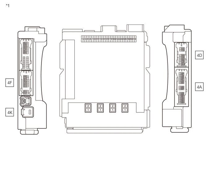
A449590C01
6.573,2.771 6.844,3.042 0.271,0.271 6.573,1.708 6.844,1.979 0.271,0.271 0.188,3.625 0.458,3.896 0.271,0.271 0.188,2.635 0.458,2.906 0.271,0.271 0.198,0.104 0.51,0.26 0.313,0.156 10 false *1 6.625,2.833 6.938,3.031 0.313,0.198 10 false 4A 6.625,1.771 6.938,1.969 0.313,0.198 10 false 4D 0.25,3.688 0.563,3.885 0.313,0.198 10 false 4K 0.25,2.688 0.563,2.885 0.313,0.198 10 false 4F
*1 Instrument Panel Junction Block Assembly - -


b.

Measure the resistance according to the value(s) in the table below.

Standard Resistance:
Tester Connection Condition Specified Condition
4K-1 - 4F-11 Battery voltage not applied 10 kΩ or higher
Battery voltage applied to terminals 4A-17 and 4D-3 Below 1 Ω


Result:
Proceed to
OK
NG


OK

15.CHECK HARNESS AND CONNECTOR (DCU (EMISSION CONTROL ECU ASSEMBLY) - INSTRUMENT PANEL JUNCTION BLOCK ASSEMBLY)

NG

REPLACE INSTRUMENT PANEL JUNCTION BLOCK ASSEMBLY

15.CHECK HARNESS AND CONNECTOR (DCU (EMISSION CONTROL ECU ASSEMBLY) - INSTRUMENT PANEL JUNCTION BLOCK ASSEMBLY)
a.
A405886C01
1.51,0.125 1.885,0.406 0.375,0.281 0.083,0.115 0.396,0.313 0.313,0.198 10 false *a 1.667,0.208 1.979,0.406 0.313,0.198 10 false E
*a Signal Check Harness No. 2 Lead Connector


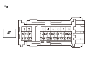
A444340C01
0.104,0.99 0.531,1.281 0.427,0.292 0.24,1.052 0.552,1.25 0.313,0.198 10 false 4F 0.135,0.146 0.448,0.302 0.313,0.156 10 false *a
*a Front view of wire harness connector
(to Instrument Panel Junction Block Assembly)


Disconnect the instrument panel junction block assembly connector.


b.

Connect the signal check harness No. 2 to the DCU (emission control ECU assembly) vehicle side harness. (Do not connect the harness to the DCU (emission control ECU assembly).)


c.

Measure the resistance according to the value(s) in the table below.

Standard Resistance:
Tester Connection Condition Specified Condition
E-26 (IGSW) - 4F-11 Always Below 1 Ω
E-26 (IGSW) or 4F-11 - Body ground and other terminals Always 10 kΩ or higher


Result:
Proceed to
OK
NG


OK

16.CHECK HARNESS AND CONNECTOR (INSTRUMENT PANEL JUNCTION BLOCK ASSEMBLY - IGNITION SWITCH ASSEMBLY, BODY GROUND)

NG

REPAIR OR REPLACE HARNESS OR CONNECTOR

16.CHECK HARNESS AND CONNECTOR (INSTRUMENT PANEL JUNCTION BLOCK ASSEMBLY - IGNITION SWITCH ASSEMBLY, BODY GROUND)
a.

Disconnect the ignition switch assembly connector.


b.

Disconnect the instrument panel junction block assembly connector.


c.

Measure the resistance according to the value(s) in the table below.

Standard Resistance:
Tester Connection Condition Specified Condition
4A-17 - J63-5 (IG1) Always Below 1 Ω
4D-3 - Body ground Always Below 1 Ω
4A-17 or J63-5 (IG1) - Body ground Always 10 kΩ or higher


Result:
Proceed to
OK
NG


OK

17.INSPECT IGNITION SWITCH ASSEMBLY

NG

REPAIR OR REPLACE HARNESS OR CONNECTOR

17.INSPECT IGNITION SWITCH ASSEMBLY
a.

Inspect the ignition switch assembly.

Click hereEngine / Hybrid System>N04C-WA (STARTING)>IGNITION SWITCH>INSPECTION


Result:
Proceed to
OK
NG


OK

REPAIR OR REPLACE POWER SOURCE CIRCUIT

NG

REPLACE IGNITION SWITCH ASSEMBLY