ENGINE HOOD / DOOR AUTO CENTER DOOR(for Glide Type) DISASSEMBLY
CAUTION / NOTICE / HINT
- HINT:
- ·
Use the same procedure for RHD and LHD vehicles.
·The procedure listed below is for RHD vehicles.
PROCEDURE

 1. PRECAUTION
- CAUTION:
-
Before disassembling and assembling the glide door, operate the power slide door main switch and check that an auto operation is not performed.
69207S
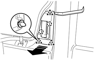
2.REMOVE REAR DOOR INSIDE HANDLE COVER

|
Remove in this Direction |
Using the moulding remover A, detach the 3 clips.
Detach the 2 claws and remove the rear door inside handle cover.
67690
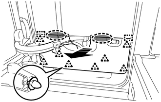
3.REMOVE GLIDE DOOR LOWER TRIM ASSEMBLY
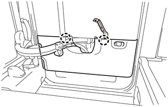
Using the moulding remover B, detach the 2 claws.

|
Place Hand Here |
|
|
Remove in this Direction |
Place your hand at the position shown in the illustration, and while pulling the gride door lower trim assembly toward you, detach the 8 clips and 2 guides to remove the gride door lower trim assembly.
67680A
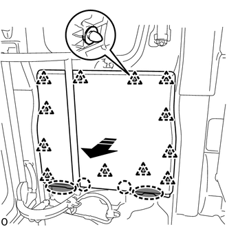
4.REMOVE GLIDE DOOR TRIM ASSEMBLY
|
|
Place Hand Here |
|
|
Remove in this Direction |
Place your hand at the position shown in the illustration, and while pulling the gride door trim assembly toward you, detach the 2 claws and 12 clips to remove the gride door trim assembly.
82153
5.DISCONNECT REAR DOOR NO. 1 WIRE
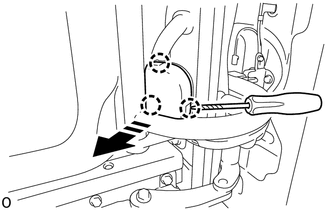
|
|
Remove in this Direction |

|
Protective Tape |
Using a screwdriver with its tip wrapped with protective tape, detach the 3 claws and remove the cover.
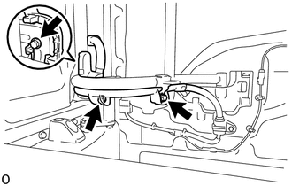
Remove the 3 bolts and disconnect the rear door No. 1 wire from the glide door arm assembly.
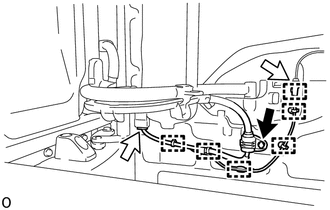

|
Bolt |

|
Connector |
Disconnect the 2 connectors and remove the bolt.
Detach the 6 clamps and disconnect the rear door No. 1 wire from the glide door assembly.
67841A
6.REMOVE GLIDE DOOR SERVICE HOLE COVER
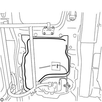
Remove the glide door service hole cover.
|
|
Remove in this Direction (1) |

|
Remove in this Direction (2) |
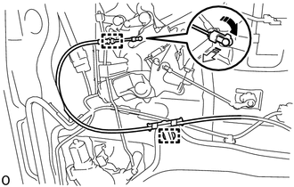
Detach the clamp and snap as shown in the illustration.
|
|
Remove in this Direction |
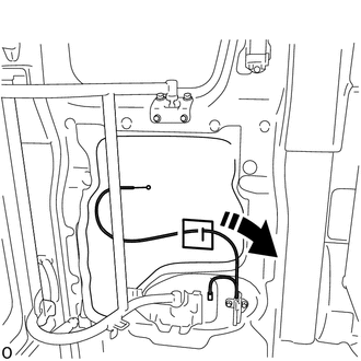
Pull out the cable of the glide door open lock assembly from the glide door service hole cover.
- HINT:
-
Remove any remaining butyl tape from the glide door assembly.
67859F
7.REMOVE GLIDE DOOR LOWER HOLE COVER
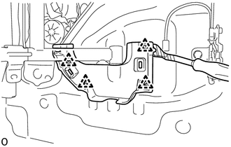
Using a clip remover, detach the 4 clips and remove the glide door lower hole cover.
69030B
8.REMOVE GLIDE DOOR OPEN LOCK ASSEMBLY
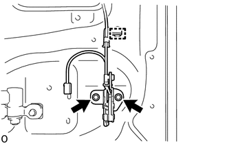
Detach the clamp.
Remove the 2 bolts and glide door open lock assembly.
85453
9.REMOVE DOOR CONTROL MOTOR
69230A
10.REMOVE GLIDE DOOR OUTSIDE HANDLE ASSEMBLY
|
|
Remove in this Direction (1) |
|
|
Remove in this Direction (2) |
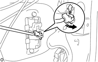
Detach the snap in the direction indicated by the arrow (1) as shown in the illustration.
Disconnect the rear door opne control link in the direction indicated by the arrow (2) as shown in the illustration.
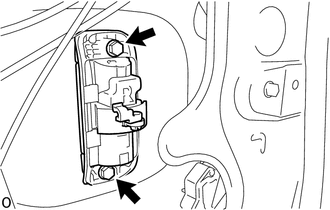
Remove 2 bolts and glide door outside handle assembly.
69714B
11.REMOVE REAR DOOR OPEN CONTROL LINK
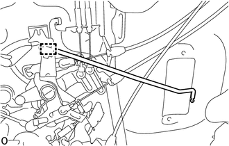
Detach the clamp and remove the rear door open control link.
69281
12.REMOVE GLIDE DOOR INSIDE HANDLE
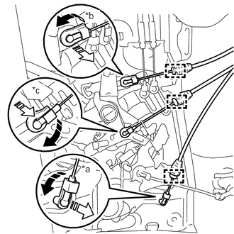
| *a | Locking Cable (Orange) |
| *b | Open Cable (Blue) |
| *c | Close Cable (Purple) |
|
|
Remove in this Direction (1) |
|
|
Remove in this Direction (2) |
Detach the clamp.
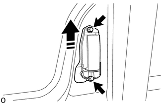
Detach the 3 snaps and disconnect the 3 cables from the glide door lock remote control assembly as shown in the illustration.
|
|
Remove in this Direction |
Remove the 2 bolts and pull out the glide door inside handle in the direction indicated by the arrow in the illustration to remove the glide door inside handle.
69530E
13.REMOVE GLIDE DOOR LOCK CYLINDER ASSEMBLY
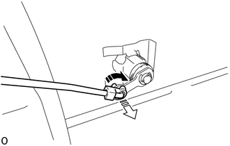
|
|
Remove in this Direction (1) |
|
|
Remove in this Direction (2) |
Detach the snap as shown in the illustration.
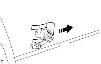
|
|
Remove in this Direction |
Remove the retainer as shown in the illustration.
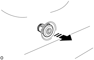
|
|
Remove in this Direction |
Remove the glide door lock cylinder assembly as shown in the illustration.
69630A
14.REMOVE GLIDE DOOR LOCK REMOTE CONTROL ASSEMBLY
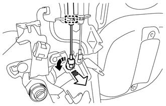
|
|
Remove in this Direction (1) |
|
|
Remove in this Direction (2) |
Detach the clamp.
Detach the snap as shown in the illustration.
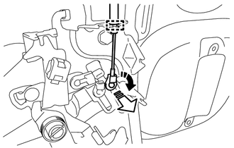
|
|
Remove in this Direction (1) |
|
|
Remove in this Direction (2) |
Detach the clamp.
Detach the snap as shown in the illustration.
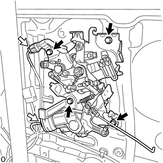
|
|
Bolt |
|
|
Connector |
Disconnect the 2 connectors.
Remove the 4 bolts and glide door lock remote control assembly.
69330B
15.REMOVE GLIDE DOOR FRONT LOCK ASSEMBLY
69340A
16.REMOVE GLIDE DOOR REAR LOCK ASSEMBLY
68750A
17.REMOVE GLIDE DOOR LINK ASSEMBLY
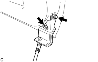
Remove the 2 bolts and disconnect the glide door link assembly from the glide door assembly.
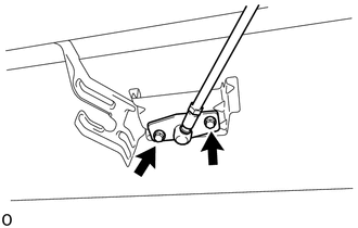
Remove the 2 bolts and glide door link assembly from the vehicle body.
68790A
18.REMOVE GLIDE DOOR ARM ASSEMBLY
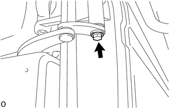
Remove the bolt.
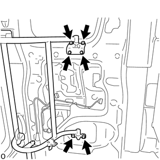
Remove the 6 bolts and disconnect the glide door arm assembly from the glide door assembly.
- NOTICE:
- ·
Do not damage the glide door assembly and vehicle body with the glide door arm assembly.
·Support the lower portion of the glide door assembly when disconnecting the glide door arm assembly, as the glide door assembly becomes unstable.
·Work with 2 or more persons when removing the glide door assemlby in order to prevent deformation and damage.
|
|
Remove in this Direction |
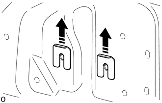
With glide door spacer installed:
Remove the 2 glide door spacers as shown in the illustration.
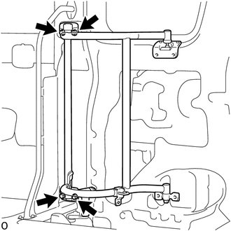
Remove the 4 bolts and glide door arm assembly.
- NOTICE:
-
Do not damage the glide door assembly and vehicle body with the glide door arm assembly.
67025A
19.REMOVE SLIDE DOOR FRONT STOPPER SUB-ASSEMBLY
|
|
Remove in this Direction |
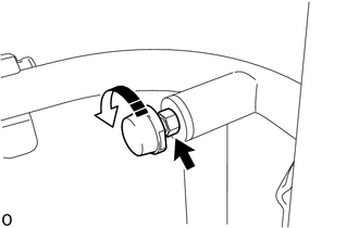
Loosen the nut and remove the slide door front stopper sub-assembly as shown in the illustration.
68799
20.REMOVE GLIDE DOOR ARM CAP
|
|
Protective Tape |
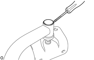
Using a screwdriver with its tip wrapped with protective tape, remove the glide door arm cap.
- HINT:
-
Use the same procedure described for the other side.
67871B
21.REMOVE GLIDE DOOR WEATHERSTRIP
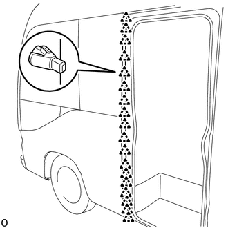
Using a screwdriver with its tip wrapped with protective tape, detach the 18 clips and remove the glide door weatherstrip.
62927
22.REMOVE GLIDE DOOR OUTER WEATHERSTRIP
- HINT:
-
Use the same procedure described for the glide door weatherstrip.
23.REMOVE HOLE PLUG
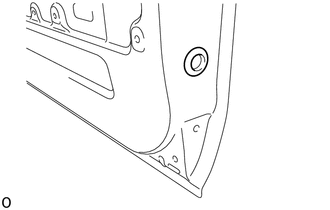
Remove the hole plug.
- HINT:
-
Use the same procedure described for the other side.