N04C-WA EMISSION CONTROL UREA PUMP REMOVAL
PROCEDURE

 77801A
1.REMOVE UREA TANK SUB-ASSEMBLY
77871A
2.REMOVE UREA PUMP
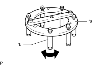
| *a | SST (Plate) |
| *b | SST (Claw) |
Temporarily install SST (claw) to SST (plate) as shown in the illustration.
- SST
- 09809-36010 (09809-03010, 09809-03020, 09809-03030, 09809-03040, 09809-03050)
- HINT:
-
Temporarily install SST (claw) within the range in which it can move.
Set 6 SSTs (claws) to the lock plate.
- NOTICE:
- ·
Align the cutout of SST (claw) with the cutout of the lock plate.
·The cutout of the lock plate around the O mark of the urea tank sub-assembly is the flanged part of the urea pump as shown in the illustration, so SST cannot be installed in this area.
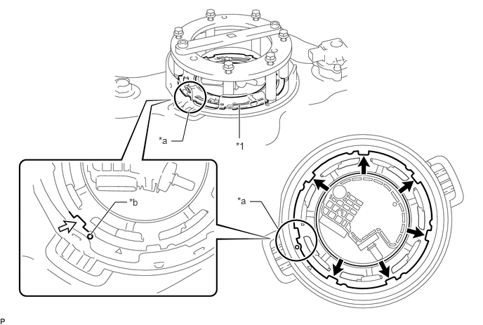
| *1 | Lock Plate | - | - |
| *a | Area (Lock Plate) Where SST (Claw) Cannot be Installed | *b | O Mark (Urea Tank Sub-assembly Side) |

|
SST (Claw) Installation Position | 
|
Position Where SST (Claw) Cannot be Installed |
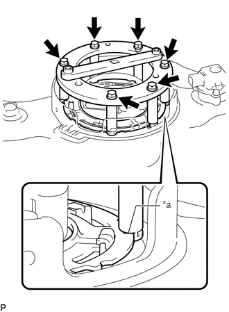
| *a | Cutout |
While pressing each SST (claw) securely against the cutout of the lock plate, tighten SST (bolt).
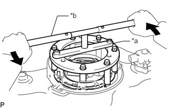
| *a | SST (Plate) |
| *b | SST (Handle) |
|
|
Loosen |
Install SST (handle) to SST (plate).
- SST
- 09808-14031 (09808-01010)
While one person loosens the lock plate, have another person hold the urea tank assembly and remove the lock plate.
- NOTICE:
- ·
Do not use any tools other than SST, such as screwdriver, etc.
·Make sure to rotate SST (handle) horizontally. If it is rotated at an angle, SST may come off.
·Do not spin SST too fast or use an impact wrench as this may result in damage to components.
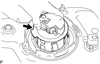
Remove the urea pump from the urea tank sub-assembly.
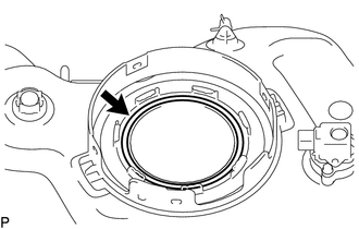
Remove the O-ring from the urea tank sub-assembly.