N04C-WA EMISSION CONTROL UREA PUMP INSTALLATION
PROCEDURE

 77871A
1.INSTALL UREA PUMP
- HINT:
-
Perform "Inspection After Repairs" after replacing the urea pump.
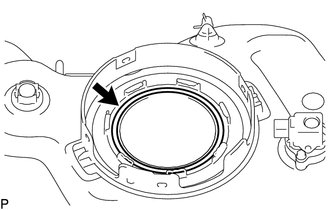
Install a new O-ring to the urea tank sub-assembly.
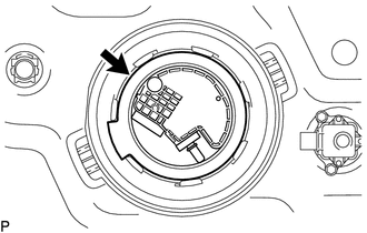
Install the urea pump to the urea tank sub-assembly as shown in the illustration.
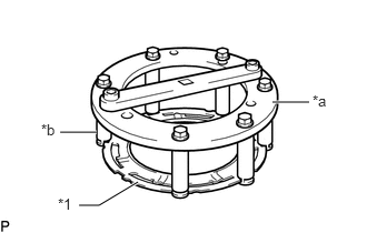
| *1 | Lock Plate |
| *a | SST (Plate) |
| *b | SST (Claw) |
Install SST (claw) and SST (plate) to the lock plate as shown in the illustration.
- SST
- 09809-36010 (09809-03010, 09809-03020, 09809-03030, 09809-03040, 09809-03050)
- NOTICE:
-
Securely install SST to the lock plate.
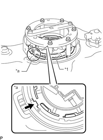
| *1 | Lock Plate |
| *a | Area (Lock Plate) Where SST (Claw) Cannot be Installed |
Set the lock plate to the urea tank sub-assembly as shown in the illustration.
- NOTICE:
-
Be careful of the area where SST (claw) cannot be installed.
Check that the cutout of the lock plate is aligned with the ▲ mark of the urea tank sub-assembly.
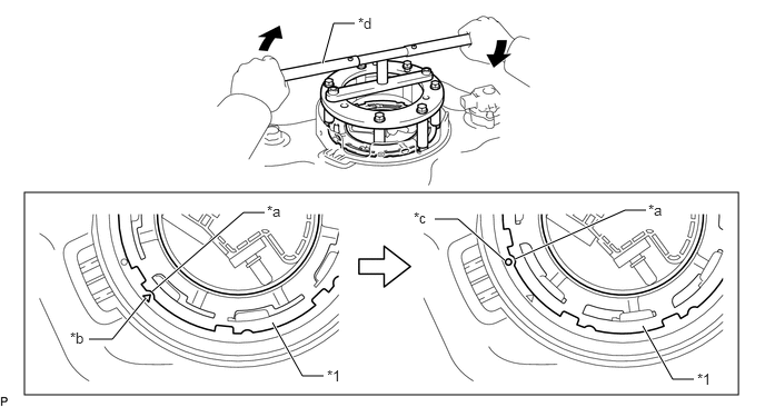
| *1 | Lock Plate | - | - |
| *a | Cutout (Lock Plate Side) | *b | ▲ Mark (Urea Tank Sub-assembly Side) |
| *c | O Mark (Urea Tank Sub-assembly Side) | *d | SST (Handle) |
Install SST (handle) to SST (plate).
- SST
- 09808-14031 (09808-01010)
Using SST, turn the cutout of the lock plate up to the O mark of the urea tank sub-assembly, and then install the urea pump assembly to the urea tank sub-assembly.
- NOTICE:
- ·
Do not use any tools other than SST, such as a screwdriver, etc.
·Be sure to keep the handle level when turning it, as SST may slip off the retainer if SST (handle) is turned at an angle with excessive force.
·Do not use an impact wrench or turn SST (handle) with excessive force, as parts may be damaged.
·If SST slips off the lock plate, loosen SST (bolt) and then reattach it.
·Be careful that the gasket does not come loose.
77801A
2.INSTALL UREA TANK SUB-ASSEMBLY