N04C-UH COOLING RADIATOR INSTALLATION
PROCEDURE

 16400B
1.INSTALL RADIATOR DRAIN COCK PLUG
Install the radiator drain cock plug to the radiator assembly.
- NOTICE:
-
Replace the O-ring if it is damaged.
16520
2.INSTALL WATER FILLER ASSEMBLY
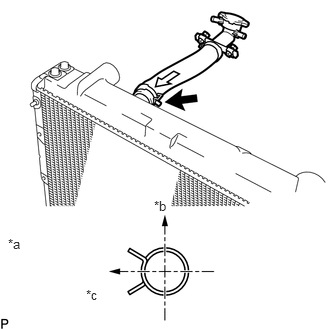
Install the water filler assembly and slide the hose clamp to secure the hose.
| *a | View A |
| *b | Upper Side |
| *c | LH Side |
- HINT:
-
Perform the installation with the hose clamp at the correct angle.
16571
3.INSTALL INLET RADIATOR HOSE
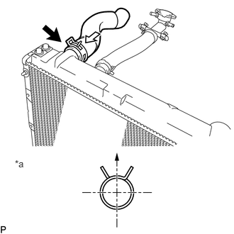
Install the inlet radiator hose and slide the hose clamp to secure the hose.
| *a | View A |
| *b | Upper Side |
- HINT:
-
Perform the installation with the hose clamp at the correct angle.
32910
4.INSTALL OIL COOLER ASSEMBLY
Install the oil cooler assembly with the 4 bolts.
- Torque:
- 12 N*m (122 kgf*cm, 9 ft.*lbf)
17940D
5.INSTALL INTERCOOLER ASSEMBLY
Install the intercooler assembly with the 2 bolts and 2 nuts.
- Torque:
- 20 N*m (204 kgf*cm, 15 ft.*lbf)
16400
6.INSTALL RADIATOR ASSEMBLY
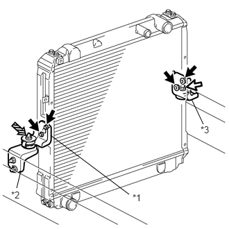
Install the radiator assembly with intercooler assembly to the vehicle.
| *1 | No. 1 Radiator Bracket |
| *2 | No. 2 Radiator Bracket |
| *3 | No. 3 Radiator Bracket |

|
Bolt A |

|
Bolt B |

|
Nut |
Install the No. 2 radiator bracket with the 2 bolts.
- Torque:
20 N*m (204 kgf*cm, 15 ft.*lbf)
Install the No. 1 radiator bracket with the 2 bolts and nut.
- Torque:
- for bolt A:
20 N*m (204 kgf*cm, 15 ft.*lbf)
- for nut:
20 N*m (204 kgf*cm, 15 ft.*lbf)
Install the No. 3 radiator bracket with the 3 bolts.
- Torque:
- for bolt A:
20 N*m (204 kgf*cm, 15 ft.*lbf)
- for bolt B:
12 N*m (122 kgf*cm, 9 ft.*lbf)
Engage the hose clamp.
Connect the vacuum transmitting hose.
53167
7.INSTALL RADIATOR BRACE ROD RH
Install the radiator brace rod RH with the bolt and nut.
- Torque:
- for bolt:
18 N*m (184 kgf*cm, 13 ft.*lbf)
- for nut:
20 N*m (204 kgf*cm, 15 ft.*lbf)
53168
8.INSTALL RADIATOR BRACE ROD LH
Install the radiator brace rod LH with the bolt and nut.
- Torque:
- for bolt:
18 N*m (184 kgf*cm, 13 ft.*lbf)
- for nut:
20 N*m (204 kgf*cm, 15 ft.*lbf)
32943A
9.INSTALL NO. 2 TRANSMISSION OIL COOLER HOSE
32943
10.INSTALL NO. 1 TRANSMISSION OIL COOLER HOSE
16520
11.CONNECT WATER FILLER ASSEMBLY
Connect the water filler assembly with the 2 bolts.
- Torque:
7.5 N*m (76 kgf*cm, 66 in.*lbf)
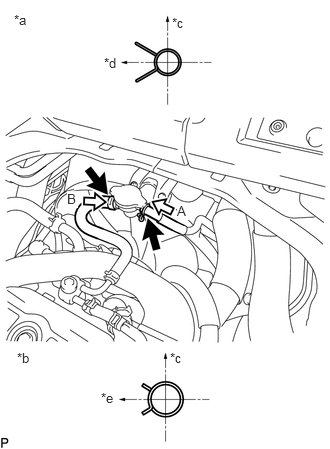
Connect the radiator reservoir hose, water by-pass hose and slide the 2 hose clamps to secure the hose.
| *a | View A |
| *b | View B |
| *c | Upper Side |
| *d | Rear Side |
| *e | Front Side |
- HINT:
-
Perform the installation with the hose clamp at the correct angle.
16571
12.CONNECT INLET RADIATOR HOSE
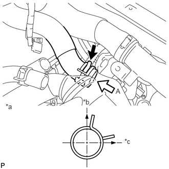
Connect the inlet radiator hose and slide the hose clamp to secure the hose.
| *a | View A |
| *b | Upper Side |
| *c | RH Side |
- HINT:
-
Perform the installation with the hose clamp at the correct angle.
17342F
13.CONNECT NO. 2 INTERCOOLER AIR HOSE
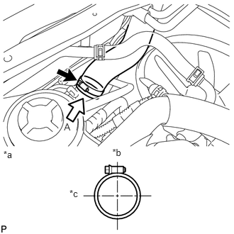
Connect the No. 2 intercooler air hose and tighten the hose clamp to secure the hose.
- Torque:
6.0 N*m (61 kgf*cm, 53 in.*lbf)
| *a | View A |
| *b | Upper Side |
| *c | LH Side |
- HINT:
- ·
Perform the installation with the hose clamp at the correct angle.
·Tighten the screw at a rate of 2 seconds per turn.
17341K
14.CONNECT NO. 1 INTERCOOLER AIR HOSE
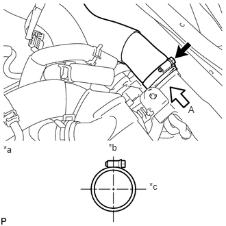
Connect the No. 1 intercooler air hose and tighten the hose clamp to secure the hose.
- Torque:
6.0 N*m (61 kgf*cm, 53 in.*lbf)
| *a | View A |
| *b | Upper Side |
| *c | RH Side |
- HINT:
- ·
Perform the installation with the hose clamp at the correct angle.
·Tighten the screw at a rate of 2 seconds per turn.
16701
15.INSTALL FAN SHROUD SUB-ASSEMBLY