N04C-UH COOLING FAN INSTALLATION
PROCEDURE

 16371
1.INSTALL FAN PULLEY
Install the fan pulley to the engine water pump assembly.
16361
2.INSTALL FAN
Install the fan to the fluid coupling assembly with the 4 nuts.
- Torque:
11 N*m (112 kgf*cm, 8 ft.*lbf)
16701
3.INSTALL FAN SHROUD SUB-ASSEMBLY (for RHD)
Temporarily install the fan shroud sub-assembly together with the fluid coupling assembly.
- NOTICE:
-
Be careful not to damage the radiator core.
Install the fan shroud sub-assembly with the 4 bolts.
- Torque:
5.0 N*m (51 kgf*cm, 44 ft.*lbf)
Install the fan and generator V belt.
Click hereEngine / Hybrid System>N04C-UH (ENGINE MECHANICAL)>DRIVE BELT>INSTALLATION
Install the fluid coupling assembly with the 4 nuts.
- Torque:
29 N*m (291 kgf*cm, 21 ft.*lbf)
Engage the 3 hose clamps and install the radiator reservoir hose.
Engage the hose clamp and install the No. 1 intercooler air hose.
16701
4.INSTALL FAN SHROUD SUB-ASSEMBLY (for LHD)
Temporarily install the fan shroud sub-assembly together with the fluid coupling assembly.
- NOTICE:
-
Be careful not to damage the radiator core.
Install the fan shroud sub-assembly with the 4 bolts.
- Torque:
5.0 N*m (51 kgf*cm, 44 ft.*lbf)
Install the fan and generator V belt.
Click hereEngine / Hybrid System>N04C-UH (ENGINE MECHANICAL)>DRIVE BELT>INSTALLATION
Install the fluid coupling assembly with the 4 nuts.
- Torque:
29 N*m (291 kgf*cm, 21 ft.*lbf)
Engage the 3 hose clamps and install the radiator reservoir hose.
Engage the hose clamp and install the No. 1 intercooler air hose.
32922
5.CONNECT NO. 1 OIL COOLER OUTLET TUBE (for Automatic Transmission)
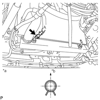
Connect the oil cooler hose to the radiator assembly with the hose clamp.
| *a | View A |
| *b | Upper Side |
- HINT:
-
Perform the installation with the hose clamp at the correct angle.
32921
6.CONNECT NO. 1 OIL COOLER INLET TUBE (for Automatic Transmission)
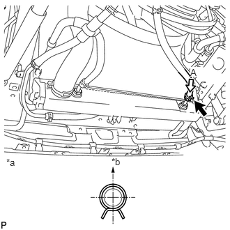
Connect the oil cooler hose to the radiator assembly with the hose clamp.
| *a | View A |
| *b | Upper Side |
- HINT:
-
Perform the installation with the hose clamp at the correct angle.
16572
7.CONNECT OUTLET RADIATOR HOSE
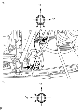
Connect the outlet radiator hose and slide the 2 hose clamps to secure the hose.
| *a | View A |
| *b | View B |
| *c | Upper Side |
| *d | RH Side |
| *e | LH Side |
- HINT:
-
Perform the installation with the hose clamp at the correct angle.
8.INSTALL NO. 1 V (COOLER COMPRESSOR TO CRANKSHAFT PULLEY) BELT (w/ Air Conditioning System)
88320
9.INSTALL COOLER COMPRESSOR ASSEMBLY (w/ Air Conditioning System)
58701A
10.INSTALL FRONT ENGINE SERVICE COVER PANEL SUB-ASSEMBLY (for LHD)
58701A
11.INSTALL FRONT ENGINE SERVICE COVER PANEL SUB-ASSEMBLY (for RHD)
33504F
12.INSTALL SHIFT LEVER SUB-ASSEMBLY (for Manual Transmission)
58841A
13.INSTALL SHIFTING HOLE COVER (for Automatic Transmission)
33503F
14.INSTALL TRANSMISSION FLOOR SHIFT ASSEMBLY (for Automatic Transmission)
33820B
15.CONNECT TRANSMISSION CONTROL CABLE ASSEMBLY (for RHD)
33820B
16.CONNECT TRANSMISSION CONTROL CABLE ASSEMBLY (for LHD)
58848A
17.INSTALL SHIFT LEVER HOLE COVER WITH BOOTS (for RHD)
33531B
18.INSTALL SHIFT AND SELECT LEVER SHAFT DUST BOOT (for LHD)
58534A
19.INSTALL TRANSMISSION COVER MAT (for Manual Transmission)
58420
20.INSTALL NO. 2 ENGINE SERVICE HOLE COVER ASSEMBLY (for Automatic Transmission)
33820B
21.INSTALL TRANSMISSION CONTROL CABLE ASSEMBLY (for Automatic Transmission)
33820B
22.ADJUST TRANSMISSION CONTROL CABLE ASSEMBLY (for Automatic Transmission)
23. SHIFT LEVER POSITION (for Automatic Transmission)
58420
24.INSTALL NO. 2 ENGINE SERVICE HOLE COVER ASSEMBLY
25.ADD ENGINE COOLANT
26.ADD AUTOMATIC TRANSMISSION FLUID
27.INSPECT AUTOMATIC TRANSMISSION FLUID LEVEL
28.INSPECT FOR COOLANT LEAK
29.INSPECT FOR OIL LEAK
58521D
30.INSTALL ENGINE SERVICE HOLE COVER MAT (w/o Carpet)
58734B
31.INSTALL ENGINE SERVICE COVER REAR WEATHERSTRIP
58410
32.INSTALL ENGINE SERVICE HOLE COVER
58521D
33.INSTALL ENGINE SERVICE HOLE COVER MAT (w/ Carpet)