PARKING BRAKE PARKING BRAKE ASSEMBLY(for Parking Brake Drum with Inner Diameter of 200 mm) REASSEMBLY
PROCEDURE

 46501A
1.REPLACE PARKING BRAKE DRUM SERRATION BOLT
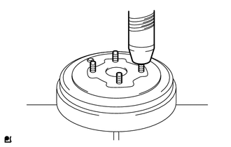
Using a press, remove the parking brake drum serration bolts.
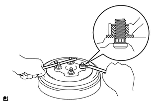
Install a washer and service nut to a new parking brake drum serration bolt as shown in the illustration.
- Recommended service nut:
- Thread diameter:
11.0 mm (0.433 in.)
- Thread pitch:
1.0 mm (0.0394 in.)
Using a brass bar or an equivalent tool to hold the parking brake drum, install the parking brake drum serration bolt by tightening the nut.
- NOTICE:
- ·
Install the nuts to prevent damage to the parking brake drum serration bolts.
·Do not damage the threads of the parking brake drum serration bolts.
2.APPLY HIGH TEMPERATURE GREASE
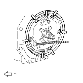
Apply high temperature grease to the surface of the parking brake plate which is in contact with the parking brake shoe.
| *1 | High Temperature Grease |
46601
3.INSTALL PARKING BRAKE SHOE LEVER SUB-ASSEMBLY
Install the parking brake shoe lever to the parking brake shoe with a new C-washer.
4.CONNECT NO. 1 PARKING BRAKE CABLE ASSEMBLY
Using needle-nose pliers, connect the No. 1 parking brake cable assembly to the parking brake shoe lever.
46405A
5.INSTALL SHOE ADJUSTING SCREW SET RH
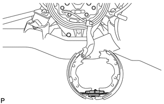
Install the parking brake shoe return tension spring and the shoe adjusting screw set to the brake shoe.
- NOTICE:
-
Install the shoe adjusting screw set so that the screw is on the left side of the vehicle when the brake shoe is installed to the parking brake.
46612
6.INSTALL PARKING BRAKE SHOE LEVER STRUT
for Type-A:
Install the parking brake shoe strut compression spring and the parking brake shoe lever strut.
Using a needle-nose pliers, install the parking brake shoe return tension spring.
for Type-B:
Install the parking brake shoe strut compression spring and the parking brake shoe lever strut.
7.INSTALL PARKING BRAKE SHOE
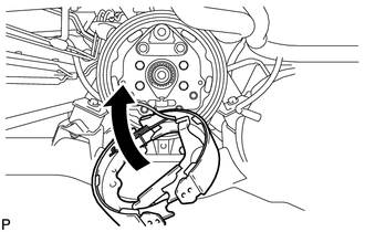
Install the parking brake shoe to the parking brake plate.
47456A
8.INSTALL PARKING BRAKE SHOE GUIDE PLATE
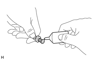
Apply adhesive to the parking brake shoe guide plate set bolt.
- Adhesive:
Toyota Genuine Adhesive 1324, Three Bond 1324 or Equivalent
Install the parking brake shoe guide plate with the parking brake shoe guide plate set bolt.
- Torque:
18 N*m (184 kgf*cm, 13 ft.*lbf)
46556
9.INSTALL SHOE HOLD DOWN SPRING PIN
Install the 2 shoe hold down spring pins, 2 shoe hold down springs and the 4 shoe hold down cups.
10.INSTALL PARKING BRAKE SHOE RETURN TENSION SPRING
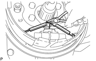
for Type-A:
Using needle-nose pliers, install the 2 parking brake shoe return tension springs.
for Type-B RHD:
Using needle-nose pliers, install the parking brake shoe return tension spring.
46201B
11.INSTALL TENSION SPRING
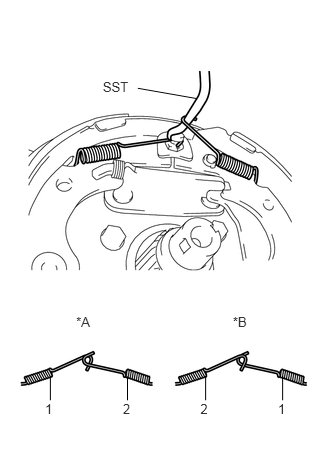
Using SST, install the 2 tension springs in the order shown in the illustration.
SST 09718-20010
| *A | for LHD |
| *B | for RHD |
12. CHECK PARKING BRAKE INSTALLATION
Check that each part is installed properly.
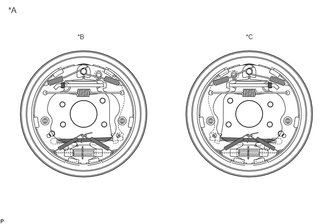
| *A | Type-A | *B | for LHD |
| *C | for RHD | - | - |
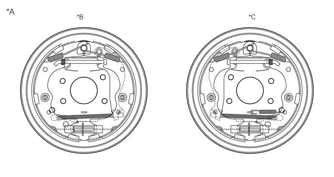
| *A | Type-B | *B | for LHD |
| *C | for RHD | - | - |
46501
13.INSTALL PARKING BRAKE DRUM SUB-ASSEMBLY
Install the parking brake drum.
- NOTICE:
-
There should be no oil or grease adhering to the friction surfaces of the shoe lining or the drum.
Apply a light coat of MP grease to a new O-ring and install the O-ring and new nut to the parking brake drum.
Using a socket wrench 32 mm, temporarily tighten the nut.
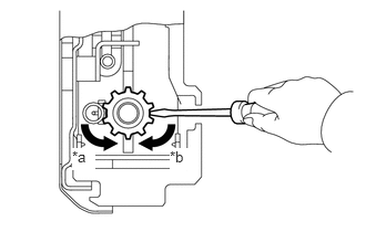
Remove the parking brake shoe adjusting hole plug, and turn the shoe adjuster to expand the shoe until the drum locks.
| *a | Expand |
| *b | Contract |
Contract the shoe adjuster until the drum rotates smoothly.
- NOTICE:
-
Ensure that the parking brake does not drag.
Install the parking brake shoe adjusting hole plug.
With the parking brake lever pulled its full distance, check to see that the drum is locked.
Release the parking brake lever and ensure that the parking brake does not drag.
If it drags, contract the shoe adjuster another notch.
Pull the parking brake lever.
Tighten the nut to the parking brake drum.
- Torque:
- for A444E:
170 N*m (1734 kgf*cm, 125 ft.*lbf)
- for A860E:
190 N*m (1937 kgf*cm, 140 ft.*lbf)
- for Manual Transmission:
127 N*m (1299 kgf*cm, 94 ft.*lbf)
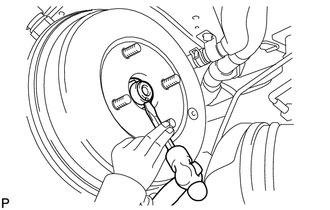
Using a chisel and a hammer, stake the nut.
Release the parking brake lever.
14.INSTALL PROPELLER SHAFT WITH CENTER BEARING ASSEMBLY
15.INSPECT AND ADJUST PARKING BRAKE LEVER TRAVEL