STEERING GEAR / LINKAGE STEERING LINKAGE INSTALLATION
PROCEDURE

 45070
1.INSTALL IDLER ARM BRACKET ASSEMBLY
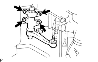
Install the idler arm bracket assembly with the 4 bolts.
- Torque:
91N*m ( 928kgf*cm , 67 ft.*lbf )
45410
2.INSTALL CENTER ARM BRACKET ASSEMBLY
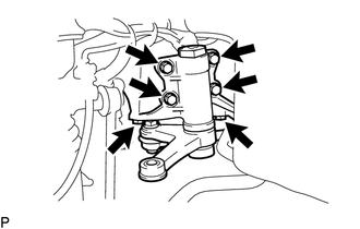
Install the center arm bracket assembly with the 6 bolts.
- Torque:
140N*m ( 1428kgf*cm , 103 ft.*lbf )
Temporarily install the nut and center arm stopper.
45440
3.CONNECT STEERING DRAG LINK ASSEMBLY
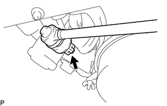
Install the steering drag link assembly to the pitman arm with the nut.
- Torque:
150N*m ( 1530kgf*cm , 111 ft.*lbf )
Install a new cotter pin.
- NOTICE:
-
Further tighten the castle nut up to 60° if the hole for the cotter pin is not aligned.
45450
4.INSTALL STEERING RELAY ROD ASSEMBLY
Pull in the steering relay rod assembly to the vehicle.
- CAUTION:
-
Do not drop the steering relay rod assembly.
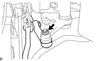
Install the steering relay rod assembly to the center arm bracket assembly with the nut.
- Torque:
150N*m ( 1530kgf*cm , 111 ft.*lbf )
Install a new cotter pin.
- NOTICE:
-
Further tighten the castle nut up to 60° if the hole for the cotter pin is not aligned.
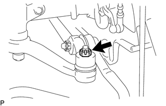
Install the steering relay rod assembly to the idler arm bracket assembly with the nut.
- Torque:
91N*m ( 928kgf*cm , 67 ft.*lbf )
Install a new cotter pin.
- NOTICE:
-
Further tighten the castle nut up to 60° if the hole for the cotter pin is not aligned.
45700
5.INSTALL STEERING DAMPER ASSEMBLY
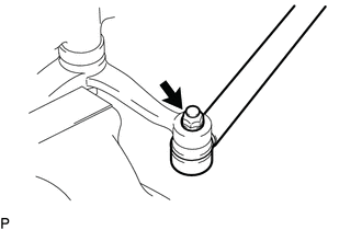
Install the steering damper assembly to the idler arm bracket with the nut .
- Torque:
74N*m ( 755kgf*cm , 55 ft.*lbf )
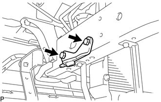
Install the steering damper bracket with the 2 bolts.
- Torque:
91N*m ( 928kgf*cm , 67 ft.*lbf )
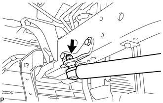
Install the steering damper assembly with the nut to the steering damper bracket.
- Torque:
74N*m ( 755kgf*cm , 55 ft.*lbf )
45047
6.INSTALL TIE ROD END SUB-ASSEMBLY LH
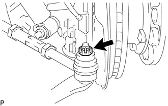
Connect the tie rod end sub-assembly LH to the knuckle arm LH with the nut.
- Torque:
150N*m ( 1530kgf*cm , 111 ft.*lbf )
Install a new cotter pin.
- NOTICE:
-
Further tighten the castle nut up to 60° if the hole for the cotter pin is not aligned.
45046
7.INSTALL TIE ROD END SUB-ASSEMBLY RH
- HINT:
-
Use the same procedure as for the LH side.
8.INSTALL NO. 1 ENGINE UNDER COVER
9.INSTALL FRONT WHEEL
10. PLACE FRONT WHEELS FACING STRAIGHT AHEAD
11.INSPECT AND ADJUST FRONT WHEEL ALIGNMENT
for 1HZ:
Click hereSuspension>ALIGNMENT / HANDLING DIAGNOSIS>FRONT WHEEL ALIGNMENT (for 1HZ)>ADJUSTMENT
for 2TR-FE:
Click hereSuspension>ALIGNMENT / HANDLING DIAGNOSIS>FRONT WHEEL ALIGNMENT (for 2TR-FE)>ADJUSTMENT
for N04C Series Engine:
Click hereSuspension>ALIGNMENT / HANDLING DIAGNOSIS>FRONT WHEEL ALIGNMENT (for N04C Series Engine)>ADJUSTMENT
for 1BZ-FPE:
Click hereSuspension>ALIGNMENT / HANDLING DIAGNOSIS>FRONT WHEEL ALIGNMENT (for 1BZ-FPE)>ADJUSTMENT
12.ADJUST CENTER ARM STOPPER
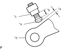
Adjust the center arm stopper so they meet the dimensions shown in the illustration when the tire exceeds 39°30 facing the inner left.
| *a | 2.0 mm (0.079 in.) |
| *b | 12.0 to 15.0 mm (0.473 to 0.590 in.) |
| *c | Nut |
| *d | Center Arm |
| *e | Center Arm Stopper |
Install the nut.
- Torque:
49N*m ( 500kgf*cm , 36 ft.*lbf )