A861E AUTOMATIC TRANSMISSION / TRANSAXLE TRANSMISSION WIRE INSTALLATION
PROCEDURE

 1.INSTALL TRANSMISSION WIRE
Coat the O-ring of a new No. 1 transmission wire with Toyota Genuine ATF type T-IV.
Pass the No. 1 transmission wire through the transmission wire installation mouth of the transmission case sub-assembly.
- NOTICE:
-
Pass the connectors attached to the end of the No. 1 transmission wire one at a time through the transmission wire installation mouth.
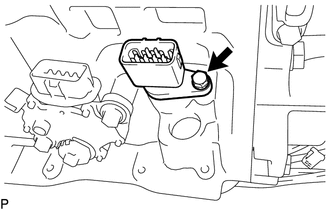
Install the No. 1 transmission wire with the bolt.
- Torque:
- 8.0 N*m (82 kgf*cm, 71 in.*lbf)
- NOTICE:
-
Make sure that the O-ring is not cracked or jammed when installing it on the transmission case sub-assembly.
Coat the O-ring of a new No. 2 transmission wire with Toyota Genuine ATF type T-IV.
Pass the No. 2 transmission wire through the transmission wire installation mouth of the transmission case sub-assembly.
- NOTICE:
-
Pass the connectors attached to the end of the No. 2 transmission wire one at a time through the transmission wire installation mouth.
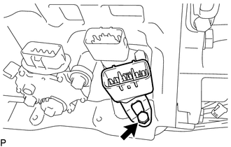
Install the No. 2 transmission wire with the bolt.
- Torque:
- 8.0 N*m (82 kgf*cm, 71 in.*lbf)
- NOTICE:
-
Make sure that the O-ring is not cracked or jammed when installing it on the transmission case sub-assembly.
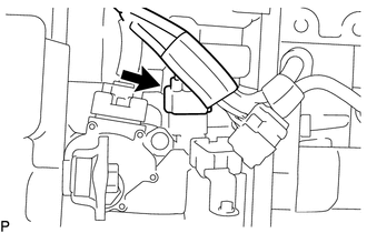
Connect the No. 1 transmission wire connector.
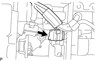
Connect the No. 2 transmission wire connector.
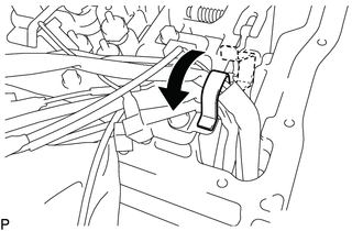
Close the cable clamp by hand as shown in the illustration and connect the transmission wire.
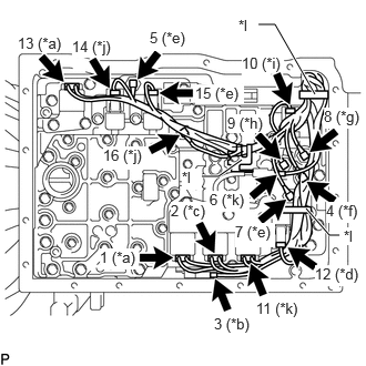
| *a | Wiring color: Blue, white |
| *b | Wiring color: Green, orange |
| *c | Wiring color: Yellow, black |
| *d | Wiring color: Green |
| *e | Wiring color: Black |
| *f | Wiring color: White |
| *g | Wiring color: Brown |
| *h | Wiring color: Pink |
| *i | Wiring color: Orange |
| *j | Wiring color: Yellow |
| *k | Wiring color: Red, brown |
| *l | Clamp |
Connect the 16 solenoid valve connectors in the order shown in the illustration.
- NOTICE:
- ·
Check that no unnecessary force is applied to the cables or connectors after inserting the connectors.
·Check that the locks are properly secured for all connectors except for the pressure switch assembly.
·Check that the rubber cover is attached before inserting the pressure switch assembly to the connector.
Click hereDrivetrain>A861E (AUTOMATIC TRANSMISSION / TRANSAXLE)>SHIFT SOLENOID VALVE>INSTALLATION
·The pressure switch assembly connector can only be inserted once. If the connector is pulled out, replace it with a new transmission wire.
·Insert the pressure switch assembly connector until it contacts the rubber cover.
Click hereDrivetrain>A861E (AUTOMATIC TRANSMISSION / TRANSAXLE)>SHIFT SOLENOID VALVE>INSTALLATION
·Stop the clamp at the points where the harness protective tubes are installed.
35330
2.INSTALL VALVE BODY OIL STRAINER ASSEMBLY
Coat the O-ring of a new valve body oil strainer assembly with Toyota Genuine ATF type T-IV.
Install the valve body oil strainer assembly to the transmission valve body assembly with the 3 bolts.
- Torque:
- 10 N*m (102 kgf*cm, 7 ft.*lbf)
- NOTICE:
-
Make sure that the O-ring is not cracked or jammed when installing it on the transmission valve body assembly.
35106
3.INSTALL AUTOMATIC TRANSMISSION OIL PAN SUB-ASSEMBLY