N04C-VJ ENGINE CONTROL ECD SYSTEM U0101 Lost Communication With TCM
DESCRIPTION
The transmission control ECU assembly receives accelerator pedal idle contact points, torque down permission, the final fuel injection volume, accelerator sensor fail-safes, 3rd/4th gear prohibited requests and the ECT shift control accelerator position from the ECM.
It also sends torque down requests, lock-up signals, reverse prohibited signals, high oil pressure idle up requests, the AT oil temperature, shift range signals and gear position signals to the ECM.
| DTC No. | Detection Item | DTC Detection Condition | Trouble Area | MIL | Memory |
|---|---|---|---|---|---|
| U0101 | Lost Communication With TCM | Diagnosis Condition:
·
Ignition switch to ON Malfunction Status: ·
No communication between ECM and TCM Malfunction Duration: ·
for 1.25 second or more (1 trip detection logic) |
·
Harness or connector ·
ECM ·
TCM |
Comes on | DTC stored |
CONFIRMATION DRIVING PATTERN
| DTC No. | DTC Detection Drive Pattern |
|---|---|
| U0101 | Ignition switch ON for 3 seconds or more. |
WIRING DIAGRAM
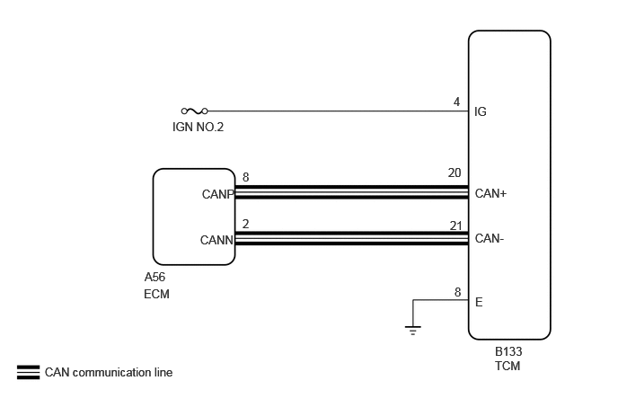
CAUTION / NOTICE / HINT
- NOTICE:
-
After replacing the ECM, the new ECM needs registration (Click hereEngine / Hybrid System>N04C-VJ (ENGINE CONTROL)>ECD SYSTEM>REGISTRATION) and initialization (Click hereEngine / Hybrid System>N04C-VJ (ENGINE CONTROL)>ECD SYSTEM>INITIALIZATION).
- HINT:
-
Read freeze frame data using the GTS. Freeze frame data records the engine condition when malfunctions are detected. When troubleshooting, freeze frame data can help determine if the vehicle was moving or stationary, if the engine was warmed up or not, and other data from the time the malfunction occurred.
PROCEDURE
Connect the GTS to DLC3.
Turn the ignition switch to ON.
Turn the GTS on.
Enter the following menus: Powertrain / Engine and ECT / Trouble Codes.
Clear the DTCs (Click hereEngine / Hybrid System>N04C-VJ (ENGINE CONTROL)>ECD SYSTEM>DTC CHECK / CLEAR).
- Result:
Proceed to NEXT
NEXT
Connect the GTS to DLC3.
Turn the ignition switch to ON.
Turn the GTS on.
Enter the following menus: Powertrain / Engine and ECT / Trouble Codes.
Read the DTCs.
- Result:
Result Proceed to DTC U0101 is output A DTC is not output B
A
B
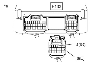
| *1 | Component with harness connected
(TCM) |
Disconnect the TCM connector.
Turn the ignition switch to ON.
Measure the voltage according to the value(s) in the table below.
- Standard Voltage:
Tester Connection Condition Specified Condition B133-4(IG) - Body ground Ignition switch ON 11 to 14 V
Measure the resistance according to the value(s) in the table below.
- Standard Resistance:
Tester Connection Condition Specified Condition B133-4(IG) - Body ground Always Below 1 Ω
- Result:
Proceed to OK NG
OK
NG
Disconnect the ECM connector.
Disconnect the TCM connector.
Measure the resistance according to the value(s) in the table below.
- Standard Resistance:
Tester Connection Condition Specified Condition A56-8(CANP) - B133-20(CAN+) Always Below 1 Ω A56-2(CANN) - B133-21(CAN-) Always Below 1 Ω
- Result:
Proceed to OK NG
OK
NG
Replace the ECM
Click hereEngine / Hybrid System>N04C-VJ (ENGINE CONTROL)>ECM>REMOVAL
- Result:
Proceed to NEXT
NEXT
Connect the GTS to DLC3.
Turn the ignition switch to ON.
Turn the GTS on.
Enter the following menus: Powertrain / Engine and ECT / Trouble Codes.
Clear the DTCs (Click hereEngine / Hybrid System>N04C-VJ (ENGINE CONTROL)>ECD SYSTEM>DTC CHECK / CLEAR).
- Result:
Proceed to NEXT
NEXT
Connect the GTS to DLC3.
Turn the ignition switch to ON.
Turn the GTS on.
Enter the following menus: Powertrain / Engine and ECT / Trouble Codes.
Read the DTCs.
- Result:
Result Proceed to DTC U0101 is output A DTC is not output B
A
B