BRAKE SYSTEM (OTHER) BRAKE MASTER CYLINDER INSTALLATION
CAUTION / NOTICE / HINT
- HINT:
- ·
Use the same procedure for RHD and LHD vehicles.
·The procedure listed below is for LHD vehicles.
PROCEDURE

 47201
1.INSTALL BRAKE MASTER CYLINDER SUB-ASSEMBLY
- NOTICE:
- ·
The master cylinder requires careful handling. Do not allow the master cylinder to receive any impact, such as from being dropped. Do not reuse a master cylinder that has been dropped.
·Do not strike or pinch the master cylinder piston, and do not cause any damage to the master cylinder piston by any other means.
·Release the vacuum from booster by depressing the brake pedal several times. Then remove the brake master cylinder from brake booster.
·When installing the brake master cylinder sub-assembly onto the brake booster, or when removing the brake master cylinder sub-assembly from the brake booster, make sure that the brake master cylinder sub-assembly is kept horizontal or its tip faces downward (the piston faces upward) to prevent the master cylinder piston from falling off.
·Do not allow any foreign objects to contaminate the master cylinder piston. If a foreign object gets on the piston, remove it by using a piece of cloth and then apply an even layer of lithium soap based glycol grease around the circumference (sliding part) of the piston.
·Do not use any other type of grease or fluid.
- HINT:
-
It not necessary to adjust the brake push rod when replacing the brake master cylinder sub-assembly.
Install a new O-ring onto the brake master cylinder sub-assembly.
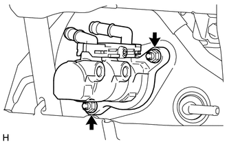
Install the brake master cylinder sub-assembly to the brake booster assembly with the 2 nuts.
- Torque:
18 N*m (184 kgf*cm, 13 ft.*lbf)
Connect the 2 master cylinder reservoir tubes with the 2 clips.
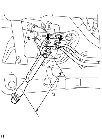
Using a union nut wrench 12 mm, install the 2 brake tubes onto the brake master cylinder sub-assembly.
- Torque:
- Specified tightening torque:
24 N*m (245 kgf*cm, 18 ft.*lbf)
- HINT:
- ·
Calculate the torque wrench reading when changing the fulcrum length of the torque wrench (Click hereGeneral>INTRODUCTION>REPAIR INSTRUCTION>PRECAUTION).
·When using a union nut wrench (fulcrum length of 20 mm (0.787 in.)) + torque wrench (fulcrum length of 180 mm (7.09 in.)): 22 N*m (224 kgf*cm, 16 ft.*lbf)
| *a | Torque Wrench Fulcrum Length |
| *b | Union Nut Wrench |
2.BLEED BRAKE SYSTEM
3.INSTALL STEERING COLUMN ASSEMBLY
83100
4.INSTALL COMBINATION METER ASSEMBLY
55480D
5.INSTALL LOWER INSTRUMENT PANEL FINISH PANEL ASSEMBLY
55412D
6.INSTALL CENTER INSTRUMENT CLUSTER FINISH PANEL