STEERING COLUMN STEERING COLUMN ASSEMBLY INSTALLATION
PROCEDURE

 45210
1.CONNECT STEERING MAIN SHAFT ASSEMBLY
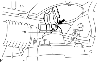
Align the matchmarks on the steering main shaft assembly and power steering gear assembly.
| *a | Matchmark |
Install the bolt.
- Torque:
36 N*m (367 kgf*cm, 27 ft.*lbf)
2.INSTALL STEERING COLUMN ASSEMBLY
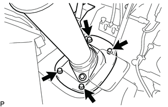
Install the No. 1 steering column hole cover sub-assembly with the 4 bolts.
- Torque:
12 N*m (122 kgf*cm, 9 ft.*lbf)
Install the steering column assembly with the 4 bolts.
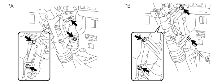
| *A | w/ Tilt Steering Column | *B | w/o Tilt Steering Column |
- Torque:
14 N*m (143 kgf*cm, 10 ft.*lbf)
Connect the wire harness clamp bracket and wire harness with the 2 bolts.
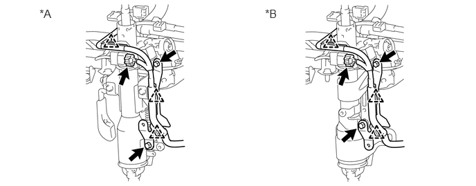
| *A | w/ Tilt Steering Column | *B | w/o Tilt Steering Column |
Connect the connector engage the 3 clamps.
58651A
3.INSTALL FRONT NO. 1 DOOR MAT PLATE
Install the front No. 1 door mat plate with the 2 screws and engage the 2 clips.
58191
4.INSTALL FRONT FLOOR FOOTREST (for RHD)
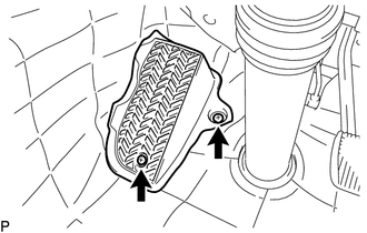
Install the front floor footrest with the 2 screws.
84140
5.INSTALL HEADLIGHT DIMMER SWITCH ASSEMBLY (w/ Airbag System)
84650
6.INSTALL WINDSHIELD WIPER SWITCH ASSEMBLY
7.INSTALL SPIRAL WITH SENSOR CABLE SUB-ASSEMBLY
45286B
8.INSTALL UPPER STEERING COLUMN COVER
Install the upper steering column cover.
45287
9.INSTALL LOWER STEERING COLUMN COVER
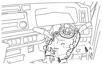
w/ Tilt Steering Column:
Engage the 6 claws and install the lower steering column cover to the upper steering column cover with the 5 screws.
- Torque:
- Screw A:
2.5 N*m (25 kgf*cm, 22 in.*lbf)
- Screw B:
2.0 N*m (20 kgf*cm, 18 in.*lbf)
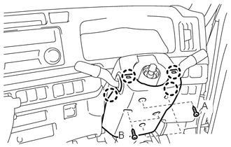
w/o Tilt Steering Column:
Engage the 4 claws and install the lower steering column cover to the upper steering column cover with the 5 screws.
- Torque:
- Screw A:
2.5 N*m (25 kgf*cm, 22 in.*lbf)
- Screw B:
2.0 N*m (20 kgf*cm, 18 in.*lbf)
10.PLACE FRONT WHEELS FACING STRAIGHT AHEAD
11.INSTALL SPIRAL WITH SENSOR CABLE SUB-ASSEMBLY (w/ Airbag System)
45100
12.INSTALL STEERING WHEEL ASSEMBLY
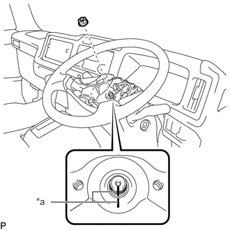
Align the matchmarks on the steering wheel assembly with the one on the steering main shaft.
| *a | Matchmark |
Install the steering wheel set nut.
- Torque:
50 N*m (510 kgf*cm, 37 ft.*lbf)
13.INSPECT STEERING WHEEL CENTER POINT
45130
14.INSTALL HORN BUTTON ASSEMBLY
52119A
15.INSTALL FRONT BUMPER COVER
w/ Snorkel Air Cleaner:
Click hereVehicle Interior>EXTERIOR>FRONT BUMPER (w/ Snorkel Air Cleaner)>INSTALLATION
w/o Snorkel Air Cleaner:
Click hereVehicle Interior>EXTERIOR>FRONT BUMPER(w/o Snorkel Air Cleaner)>INSTALLATION
16.INSTALL HEADLIGHT ASSEMBLY LH (for LHD)
for Single Beam Headlight:
Click hereVehicle Interior>LIGHTING>HEADLIGHT ASSEMBLY(for Single Beam Headlight)>INSTALLATION
for Dual Beam Headlight:
Click hereVehicle Interior>LIGHTING>HEADLIGHT ASSEMBLY(for Dual Beam Headlight)>INSTALLATION
17.INSTALL HEADLIGHT ASSEMBLY RH (for RHD)
- HINT:
-
Use the same procedure as for the LH side.
45130
18.INSPECT HORN BUTTON ASSEMBLY
19.CONNECT CABLE TO NEGATIVE BATTERY TERMINAL
20.INSPECT STEERING LOCK OPERATION
Check that the steering lock mechanism is activated when removing the key.
Check that the steering lock mechanism is deactivated when inserting the key and turning to ACC position.
21.INSPECT STEERING TILT OPERATION
22.INSPECT SRS WARNING LIGHT (w/ Airbag System)
for 2 connectors Type:
for 3 connectors Type: