AIR CONDITIONING CONDENSER REASSEMBLY
PROCEDURE

 88454B
1.INSTALL FAN SHROUD
88550D
2.INSTALL BLOWER MOTOR ASSEMBLY
88453A
3.INSTALL COOLING FAN
88454A
4.INSTALL FAN SHROUD
88590B
5.INSTALL BLOWER ASSEMBLY WITH SHROUD
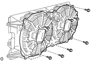
Install the 2 blower assembly with shrouds with the 8 bolts.
- Torque:
- 7.1 N*m (72 kgf*cm, 63 in.*lbf)
88605J
6.INSTALL AIR CONDITIONING WIRING HARNESS SUB-ASSEMBLY
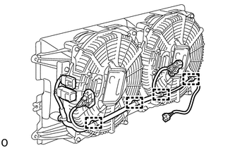
Attach the 4 wire harness clamps and install the air conditioning wiring harness sub-assembly.
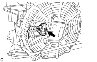
Connect the connector.
- HINT:
-
Use the same procedure for the other side.
Attach the wire harness clamp.
- HINT:
-
Use the same procedure for the other side.
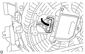
Move the connector cover as shown in the illustration.
- HINT:
-
Use the same procedure for the other side.
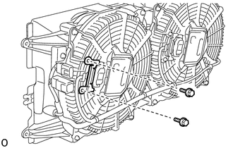
Install the bracket with the 2 bolts.
- HINT:
-
Use the same procedure for the other side.
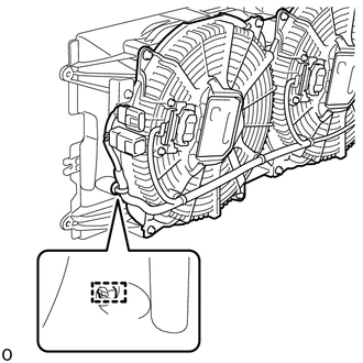
Attach the wire harness clamp.
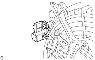
Attach the 2 claws.
88461A
7.INSTALL COOLER CONDENSER CORE
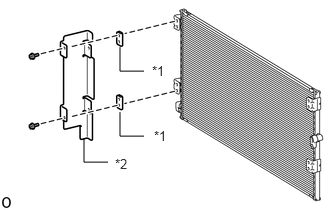
| *1 | No. 4 Cooler Condenser Bracket |
| *2 | Bracket Sub-assembly |
Install the bracket sub-assembly and 2 No. 4 cooler condenser brackets to the cooler condenser core with the 2 bolts.
- Torque:
- 5.0 N*m (51 kgf*cm, 44 in.*lbf)
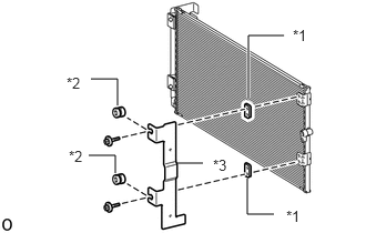
| *1 | No. 4 Cooler Condenser Bracket |
| *2 | Grommet |
| *3 | Bracket Sub-assembly |
Install the 2 grommets, bracket sub-assembly and 2 No. 4 cooler condenser brackets to the cooler condenser core with the 2 bolts.
- Torque:
- 5.0 N*m (51 kgf*cm, 44 in.*lbf)
88461C
8.INSTALL NO. 2 COOLER CONDENSER CORE
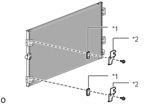
| *1 | No. 4 Cooler Condenser Bracket |
| *2 | Bracket |
Install the 2 No. 4 cooler condenser brackets and 2 brackets to the No. 2 cooler condenser core with the 2 bolts.
- Torque:
- 5.0 N*m (51 kgf*cm, 44 in.*lbf)
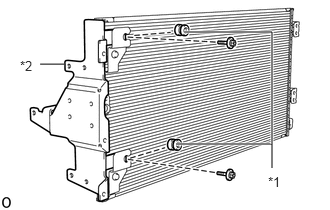
| *1 | Grommet |
| *2 | Bracket Sub-assembly |
Install the 2 grommets and bracket sub-assembly to the No. 2 cooler condenser core with the 2 bolts.
- Torque:
- 5.0 N*m (51 kgf*cm, 44 in.*lbf)
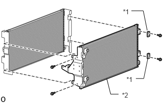
| *1 | No. 4 Cooler Condenser Bracket |
| *2 | No. 2 Cooler Condenser Core |
Install the 2 No. 4 cooler condenser brackets and No. 2 cooler condenser core to the cooler condenser core with the 4 bolts.
- Torque:
- 5.0 N*m (51 kgf*cm, 44 in.*lbf)
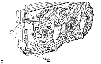
Install the fan shroud with blower assembly with the 3 bolts.
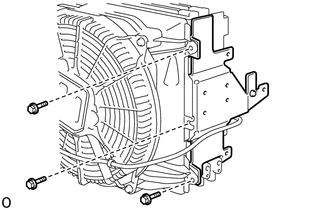
Install the bracket sub-assembly with the 3 bolts.
9.INSTALL NO. 2 COOLER PACKING
Clean the condenser assembly surface.
Remove any remaining double-sided tape from the condenser assembly.
Wipe off any tape adhesive residue with cleaner.
Heat the condenser assembly and No. 2 cooler packing using a heat light.
- CAUTION:
- ·
Do not touch the heat light and heated parts.
·Touching the heat light may result in burns.
·Touching heated parts for a long time may result in burns.
- Standard:
Item Temperature No. 2 Cooler Packing 20 to 30°C (68 to 86°F) Condenser Assembly 40 to 60°C (104 to 140°F)
Remove the peeling paper of a new No. 2 cooler packing trying not to touch the adhesional surface.
- NOTICE:
-
After removing the peeling paper, do not touch the surface of the tape with your fingers or cotton work gloves.
Align the No. 2 cooler packing as shown in the illustration.
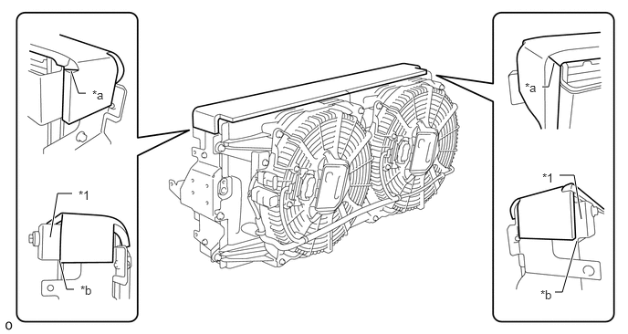
| *1 | Bracket Sub-assembly | - | - |
| *a | No. 2 Cooler Packing Cutout | *b | Point A |
- HINT:
- ·
Align the cutout of the No. 2 cooler packing with the corner of the condenser assembly.
·Align the edge of the No. 2 cooler packing with point A of the bracket sub-assembly.
·Firmly press the No. 2 cooler packing.
88715A
10.INSTALL COOLER REFRIGERANT DISCHARGE PIPE A
Remove the vinyl tape wrapped around the connection of the cooler refrigerant discharge pipe A and No. 2 cooler condenser core.
Sufficiently apply compressor oil to a new O-ring and the fitting surface of the cooler refrigerant discharge pipe A and No. 2 cooler condenser core.
- Compressor Oil:
ND-OIL 8 or equivalent
- NOTICE:
-
Do not use any compressor oil other than ND-OIL 8 or equivalent. If any compressor oil other than ND-OIL 8 or equivalent is used, compressor motor insulation performance may decrease, resulting in leakage of electric power.
Install the O-ring to the cooler refrigerant discharge pipe A.
- NOTICE:
-
Keep the O-rings and O-ring fitting surfaces free from foreign matter.
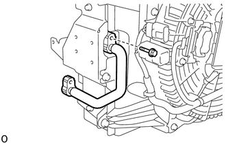
Install the cooler refrigerant discharge pipe A with the bolt.
- NOTICE:
- ·
Do not apply excessive force to the cooler refrigerant discharge pipe A.
·Make sure not to cut the O-ring while installing it. (Cut O-rings cannot be installed)
- Torque:
- 5.4 N*m (55 kgf*cm, 48 in.*lbf)
88715B
11.INSTALL COOLER REFRIGERANT DISCHARGE PIPE B
Remove the vinyl tape wrapped around the connection of the cooler refrigerant discharge pipe B and cooler refrigerant liquid pipe A, cooler condenser core.
Sufficiently apply compressor oil to 2 new O-rings and the fitting surface of the cooler refrigerant discharge pipe B, cooler refrigerant liquid pipe A and cooler condenser core.
- Compressor Oil:
ND-OIL 8 or equivalent
- NOTICE:
-
Do not use any compressor oil other than ND-OIL 8 or equivalent. If any compressor oil other than ND-OIL 8 or equivalent is used, compressor motor insulation performance may decrease, resulting in leakage of electric power.
Install the 2 O-rings to the cooler refrigerant discharge pipe B.
- NOTICE:
-
Keep the O-rings and O-ring fitting surfaces free from foreign matter.
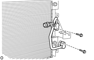
Install the cooler refrigerant discharge pipe B with the 2 bolts.
- NOTICE:
- ·
Do not apply excessive force to the cooler refrigerant discharge pipe B.
·Make sure not to cut the O-ring while installing it. (Cut O-rings cannot be installed)
- Torque:
- 5.4 N*m (55 kgf*cm, 48 in.*lbf)
12.INSTALL PIPING CLAMP
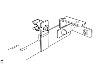
Attach the 2 claws and install the piping clamp.
88716A
13.INSTALL COOLER REFRIGERANT LIQUID PIPE A
Remove the vinyl tape wrapped around the connection of the cooler refrigerant liquid pipe A, No. 2 cooler condenser core and cooler condenser core.
Sufficiently apply compressor oil to 2 new O-rings and the fitting surface of the cooler refrigerant liquid pipe A, No. 2 cooler condenser core and cooler condenser core.
- Compressor Oil:
ND-OIL 8 or equivalent
- NOTICE:
-
Do not use any compressor oil other than ND-OIL 8 or equivalent. If any compressor oil other than ND-OIL 8 or equivalent is used, compressor motor insulation performance may decrease, resulting in leakage of electric power.
Install the 2 O-rings to the cooler refrigerant liquid pipe A.
- NOTICE:
-
Keep the O-rings and O-ring fitting surfaces free from foreign matter.
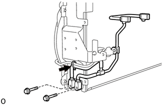
Install the cooler refrigerant liquid pipe A with the 2 bolts.
- NOTICE:
- ·
Do not apply excessive force to the cooler refrigerant liquid pipe A.
·Make sure not to cut the O-ring while installing it. (Cut O-rings cannot be installed)
- Torque:
- 5.4 N*m (55 kgf*cm, 48 in.*lbf)
Install a new strap.
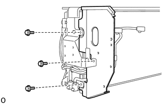
Install the dust cover with the 3 bolts.
- Torque:
- 5.0 N*m (51 kgf*cm, 44 in.*lbf)
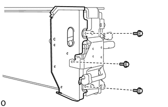
Install the dust cover with the 3 bolts.
- Torque:
- 5.0 N*m (51 kgf*cm, 44 in.*lbf)
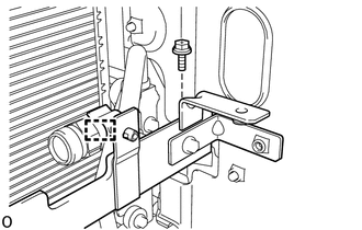
Attach the clamp and temporarily install the bracket sub-assembly.
Install the bracket sub-assembly with the bolt.
- Torque:
- 5.0 N*m (51 kgf*cm, 44 in.*lbf)
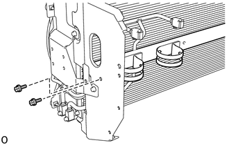
Install the 2 bolts.
- Torque:
- 5.0 N*m (51 kgf*cm, 44 in.*lbf)
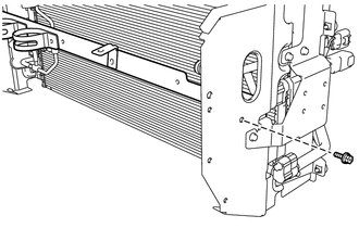
Install the bolt.
- Torque:
- 5.0 N*m (51 kgf*cm, 44 in.*lbf)
88645H
14.INSTALL NO. 1 PRESSURE SWITCH
88471
15.INSTALL RECEIVER AIR CONDITIONING TANK
88716M
16.INSTALL COOLER REFRIGERANT LIQUID PIPE M
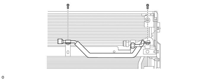
Install the cooler refrigerant liquid pipe M with the 2 bolts.
- NOTICE:
-
Do not apply excessive force to the cooler refrigerant liquid pipe M.
- Torque:
- 5.0 N*m (51 kgf*cm, 44 in.*lbf)
88716B
17.INSTALL COOLER REFRIGERANT LIQUID PIPE B
Remove the vinyl tape wrapped around the connection of the cooler refrigerant liquid pipe B and cooler refrigerant liquid pipe M.
Sufficiently apply compressor oil to new O-rings and the fitting surface of the cooler refrigerant liquid pipe M and cooler refrigerant liquid pipe B.
- Compressor Oil:
ND-OIL 8 or equivalent
- NOTICE:
-
Do not use any compressor oil other than ND-OIL 8 or equivalent. If any compressor oil other than ND-OIL 8 or equivalent is used, compressor motor insulation performance may decrease, resulting in leakage of electric power.
Install the O-ring to the cooler refrigerant liquid pipe M.
- NOTICE:
-
Keep the O-rings and O-ring fitting surfaces free from foreign matter.
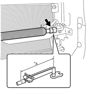
| *a | Torque Wrench Fulcrum Length |
Using a union nut wrench 19 mm, tighten the nut and connect the cooler refrigerant liquid pipe B.
- NOTICE:
- ·
Do not apply excessive force to the cooler refrigerant liquid pipe B.
·Make sure not to cut the O-ring while installing it. (Cut O-rings cannot be installed)
- Torque:
- Specified tightening torque : 13.5 N*m (138 kgf*cm, 10 ft.*lbf)
- HINT:
- ·
Calculate the torque wrench reading when changing the fulcrum length of the torque wrench.
Click hereGeneral>INTRODUCTION>REPAIR INSTRUCTION>PRECAUTION
·When using a union nut wrench (fulcrum length of 30 mm (1.18 in.)) + torque wrench (fulcrum length of 162 mm (6.38 in.)): 11.4 N*m (116 kgf*cm, 8 ft.*lbf)
88716L
18.INSTALL COOLER REFRIGERANT LIQUID PIPE L
Remove the vinyl tape wrapped around the connection of the cooler refrigerant liquid pipe L and receiver air conditioning tank.
Sufficiently apply compressor oil to 3 new O-rings and the fitting surface of the cooler refrigerant liquid pipe L and receiver air conditioning tank.
- Compressor Oil:
ND-OIL 8 or equivalent
- NOTICE:
-
Do not use any compressor oil other than ND-OIL 8 or equivalent. If any compressor oil other than ND-OIL 8 or equivalent is used, compressor motor insulation performance may decrease, resulting in leakage of electric power.
Install the 3 O-rings to the cooler refrigerant liquid pipe B.
- NOTICE:
-
Keep the O-rings and O-ring fitting surfaces free from foreign matter.
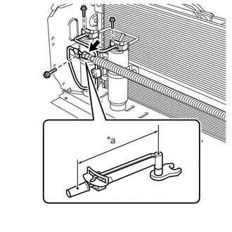
| *a | Torque Wrench Fulcrum Length |
Temporarily install the cooler refrigerant liquid pipe L with the 3 bolts and nut.
Tighten the 3 bolts.
- NOTICE:
- ·
Do not apply excessive force to the cooler refrigerant liquid pipe L.
·Make sure not to cut the O-ring while installing it. (Cut O-rings cannot be installed)
- Torque:
- 5.0 N*m (51 kgf*cm, 44 in.*lbf)
Using a union nut wrench 19 mm, tighten the nut and connect the cooler refrigerant liquid pipe L.
- NOTICE:
- ·
Do not apply excessive force to the cooler refrigerant liquid pipe L.
·Make sure not to cut the O-ring while installing it. (Cut O-rings cannot be installed)
- Torque:
- Specified tightening torque : 13.5 N*m (138 kgf*cm, 10 ft.*lbf)
- HINT:
- ·
Calculate the torque wrench reading when changing the fulcrum length of the torque wrench.
Click hereGeneral>INTRODUCTION>REPAIR INSTRUCTION>PRECAUTION
·When using a union nut wrench (fulcrum length of 30 mm (1.18 in.)) + torque wrench (fulcrum length of 162 mm (6.38 in.)): 11.4 N*m (116 kgf*cm, 8 ft.*lbf)
88715K
19.INSTALL DISCHARGE TUBE K
Remove the vinyl tape wrapped around the connection of the cooler refrigerant discharge pipe B and discharge tube K.
Sufficiently apply compressor oil to a new O-ring and the fitting surface of the cooler refrigerant discharge pipe B and discharge tube K.
- Compressor Oil:
ND-OIL 8 or equivalent
- NOTICE:
-
Do not use any compressor oil other than ND-OIL 8 or equivalent. If any compressor oil other than ND-OIL 8 or equivalent is used, compressor motor insulation performance may decrease, resulting in leakage of electric power.
Install the O-ring to the discharge tube K.
- NOTICE:
-
Keep the O-rings and O-ring fitting surfaces free from foreign matter.
Using SST, tighten the nut and install the discharge tube K.
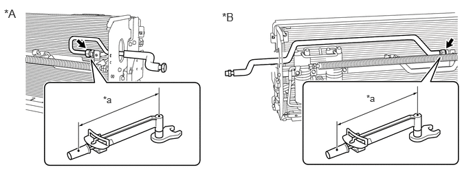
| *A | for RHD | *B | for LHD |
| *a | Torque Wrench Fulcrum Length | - | - |
- SST
- 09922-10240
- NOTICE:
- ·
Do not apply excessive force to the discharge tube K.
·Make sure not to cut the O-ring while installing it. (Cut O-rings cannot be installed)
- Torque:
- Specified tightening torque : 22.5 N*m (229 kgf*cm, 17 ft.*lbf)
- HINT:
- ·
Calculate the torque wrench reading when changing the fulcrum length of the torque wrench.
Click hereGeneral>INTRODUCTION>REPAIR INSTRUCTION>PRECAUTION
·When using SST (fulcrum length of 40 mm (1.58 in.)) + torque wrench (fulcrum length of 180 mm (7.09 in.)): 18.4 N*m (188 kgf*cm, 14 ft.*lbf)
88716P
20.INSTALL COOLER REFRIGERANT LIQUID PIPE P
Remove the vinyl tape wrapped around the connection of the cooler refrigerant liquid pipe P and cooler refrigerant liquid pipe M.
Sufficiently apply compressor oil to a new O-ring and the fitting surface of the cooler refrigerant liquid pipe P and cooler refrigerant liquid pipe M.
- Compressor Oil:
ND-OIL 8 or equivalent
- NOTICE:
-
Do not use any compressor oil other than ND-OIL 8 or equivalent. If any compressor oil other than ND-OIL 8 or equivalent is used, compressor motor insulation performance may decrease, resulting in leakage of electric power.
Install the O-ring to the cooler refrigerant liquid pipe P.
- NOTICE:
-
Keep the O-rings and O-ring fitting surfaces free from foreign matter.
for RHD:
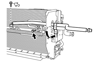

|
Bolt (A) |

|
Bolt (B) |
Install the cooler refrigerant liquid pipe P with the bolt (B).
- NOTICE:
- ·
Do not apply excessive force to the cooler refrigerant liquid pipe P.
·Make sure not to cut the O-ring while installing it. (Cut O-rings cannot be installed)
- Torque:
- 5.4 N*m (55 kgf*cm, 48 in.*lbf)
Move the No. 1 piping clamp in the direction shown in the illustration and install the No. 1 piping clamp with the bolt (A).
for LHD:
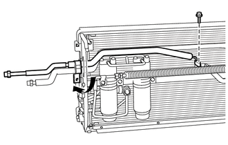
Install the cooler refrigerant liquid pipe P with the bolt.
- NOTICE:
- ·
Do not apply excessive force to the cooler refrigerant liquid pipe P.
·Make sure not to cut the O-ring while installing it. (Cut O-rings cannot be installed)
- Torque:
- 5.4 N*m (55 kgf*cm, 48 in.*lbf)
Move the No. 1 piping clamp in the direction shown in the illustration.
88463A
21.INSTALL NO. 2 COOLER CONDENSER BRACKET
Install the No. 2 cooler condenser bracket with the 4 bolts.
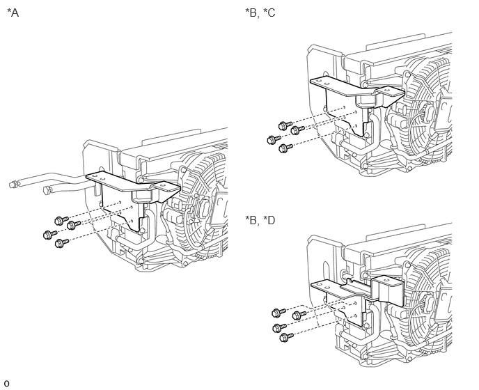
| *A | for RHD | *B | for LHD |
| *C | except Normal Body | *D | for Normal Body |
Install the 3 No. 1 cooler condenser cushions, 3 No. 2 cooler condenser cushions and 3 No. 1 condenser bracket collars.
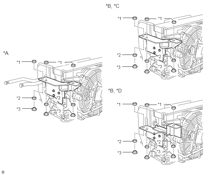
| *A | for RHD | *B | for LHD |
| *C | except Normal Body | *D | for Normal Body |
| *1 | No. 1 Cooler Condenser Cushion | *2 | No. 2 Cooler Condenser Cushion |
| *3 | No. 1 Condenser Bracket Collar | - | - |
88463B
22.INSTALL NO. 3 COOLER CONDENSER BRACKET
for RHD:
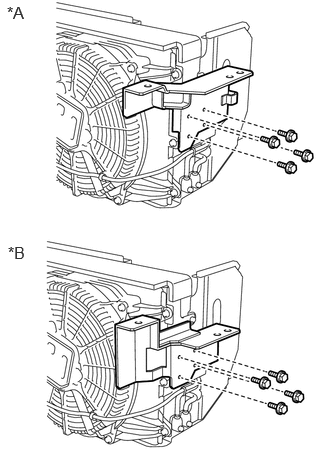
| *A | except Normal Body |
| *B | for Normal Body |
Install the No. 3 cooler condenser bracket with the 4 bolts.
for LHD:
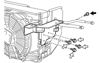
|
|
Bolt (A) |
|
|
Bolt (B) |
Install the No. 3 cooler condenser bracket with the 4 bolts (B).
Install the bolt (A).
Install the 3 No. 1 cooler condenser cushions, 3 No. 2 cooler condenser cushions and 3 No. 1 condenser bracket collars.
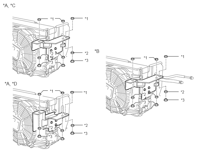
| *A | for RHD | *B | for LHD |
| *C | except Normal Body | *D | for Normal Body |
| *1 | No. 1 Cooler Condenser Cushion | *2 | No. 2 Cooler Condenser Cushion |
| *3 | No. 1 Condenser Bracket Collar | - | - |