OTHER SYSTEM POWER OUTLET SOCKET INSTALLATION
PROCEDURE

 85535B
1.INSTALL NO. 1 POWER OUTLET SOCKET COVER
Attach the claw and install the No. 1 power outlet socket cover.
85530
2.INSTALL NO. 1 POWER OUTLET SOCKET ASSEMBLY
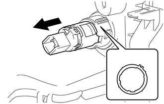
Align the cutout hole of the No. 1 power outlet socket cover and temporarily install the No. 1 power outlet socket assembly to the No. 1 power outlet socket cover as shown in the illustration.
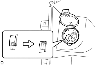
Attach the claw and install the No. 1 power outlet socket assembly as shown in the illustration.
55601C
3.INSTALL INSTRUMENT PANEL UNDER TRAY SUB-ASSEMBLY
55470
4.INSTALL INSTRUMENT CLUSTER FINISH PANEL GARNISH ASSEMBLY
55412D
5.INSTALL CENTER INSTRUMENT CLUSTER FINISH PANEL
55433B
6.INSTALL LOWER NO. 2 INSTRUMENT PANEL FINISH PANEL
58841A
7.INSTALL SHIFTING HOLE COVER (for Automatic Transmission)
58848A
8.INSTALL SHIFT LEVER HOLE COVER (for Manual Transmission)
33555D
9.INSTALL SHIFT LEVER BOOT (for Manual Transmission)
58534A
10.INSTALL TRANSMISSION COVER MAT (for Manual Transmission)
33504F
11.INSTALL SHIFT LEVER KNOB SUB-ASSEMBLY (for Manual Transmission)