AIR CONDITIONING AIR CONDITIONING PANEL INSTALLATION
CAUTION / NOTICE / HINT
- HINT:
- ·
Use the same procedure for LHD and RHD vehicles.
·The procedure listed below is for RHD vehicles.
·A bolt without a torque specification is shown in thestandard bolt chart.
Click hereGeneral>SPECIFICATIONS>STANDARD BOLT>SPECIFIED TORQUE FOR STANDARD BOLTS
PROCEDURE

 55900
1.INSTALL AIR CONDITIONING CONTROL ASSEMBLY
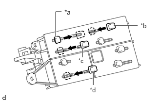
Set the defroster damper control lever in "DEF mode".
Set the air inlet damper control lever in "RECIRC mode".
Set the air mix damper control lever in "COOL mode".
Set the water valve control lever in "COOL mode".
| *a | Defroster Damper Control Lever |
| *b | Air Inlet Damper Control Lever |
| *c | Air Mix Damper Control Lever |
| *d | Water Valve Control Lever |
Connect the connectors.
Set the air conditioner control assembly on the vehicle.
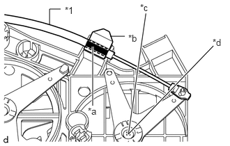
Connect the air inlet damper control cable sub-assembly:
Connect the end of the air inlet damper control cable sub-assembly inner cable to the control lever.
Secure the air mix damper control cable sub-assembly by aligning the marking with the clamp.
- NOTICE:
-
Operate the air inlet damper control lever and check that there is a sense of moderation on both ends of FRESH - RECIRC and that there is no return.
| *1 | Air Inlet Damper Control Cable Sub-assembly |
| *a | Marking Part |
| *b | Clamp Part |
| *c | FRESH |
| *d | RECIRC |
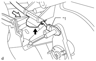
Connect the air inlet damper control cable sub-assembly, pull the outer cable of the air inlet damper control cable sub-assembly in the direction of the arrow shown in the illustration and secure it with the clamp.
- NOTICE:
-
Operate the air inlet damper control lever and check that there is a sense of moderation on both ends of FRESH - RECIRC and that there is no return.
| *1 | Air Inlet Damper Control Cable Sub-assembly |

|
Clamp Part |

|
Pulling Direction |
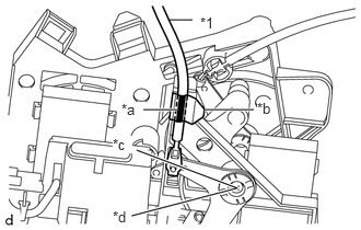
Connect the water valve control cable sub-assembly:
Connect the end of the water valve control cable sub-assembly inner cable to the control lever.
Secure the water valve control cable sub-assembly by aligning the marking with the clamp.
- NOTICE:
-
Operate the water valve control lever and check that there is a sense of moderation on both ends of MAX COOL - MAX HOT and that there is no return.
| *1 | Water Valve Control Cable Sub-assembly |
| *a | Marking Part |
| *b | Clamp Part |
| *c | MAX HOT |
| *d | MAX COOL |
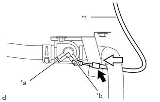
Set the water valve lever in the closed position, connect the water valve control cable sub-assembly, pull the outer cable of the water valve control cable sub-assembly in the direction of the arrow shown in the illustration and secure it with the clamp.
- NOTICE:
-
Operate the water valve control lever and check that there is a sense of moderation on both ends of MAX COOL - MAX HOT and that there is no return.
| *1 | Water Valve Control Cable Sub-assembly |
| *a | Opened Position |
| *b | Closed Position |
|
|
Clamp Part |
|
|
Pulling Direction |
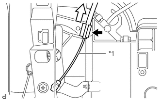
Connect the defroster damper control cable sub-assembly:
Connect the defroster damper control cable sub-assembly, pull the outer cable of the defroster damper control cable sub-assembly in the direction of the arrow shown in the illustration and secure it with the clamp.
- NOTICE:
-
Operate the defroster damper control lever and check that there is a sense of moderation on both ends of FACE - DEF and that there is no return.
| *1 | Defroster Damper Control Cable Sub-assembly |
|
|
Clamp Part |
|
|
Pulling Direction |
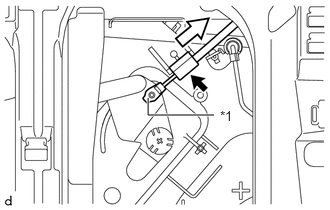
Connect the air mix damper control cable sub-assembly:
Connect the air mix damper control cable sub-assembly, pull the outer cable of the air mix damper control cable sub-assembly in the direction of the arrow shown in the illustration and secure it with the clamp.
- NOTICE:
-
Operate the air mix damper control lever and check that there is a sense of moderation on both ends of MAX COOL - MAX HOT and that there is no return.
| *1 | Air Mix Damper Control Cable Sub-assembly |
|
|
Clamp Part |
|
|
Pulling Direction |
Install the air conditioner control assembly with the 4 bolts.
55601C
2.INSTALL INSTRUMENT PANEL UNDER TRAY SUB-ASSEMBLY
55470
3.INSTALL INSTRUMENT CLUSTER FINISH PANEL GARNISH ASSEMBLY
55412D
4.INSTALL CENTER INSTRUMENT CLUSTER FINISH PANEL
86250
5.INSTALL AMPLIFIER MICROPHONE ASSEMBLY (w/ Microphone)
55433B
6.INSTALL LOWER NO. 2 INSTRUMENT PANEL FINISH PANEL
58123A
7.INSTALL SHIFT AND SELECT LEVER SUPPORT (for Manual Transmission)
58286
8.INSTALL NO. 1 SHIFT AND SELECT LEVER BOOT (for Manual Transmission)
58534A
9.INSTALL TRANSMISSION COVER MAT (for Manual Transmission)
33504F
10.INSTALL SHIFT LEVER KNOB SUB-ASSEMBLY (for Manual Transmission)
58841A
11.INSTALL SHIFTING HOLE COVER (for Automatic Transmission)
55410C
12.INSTALL INSTRUMENT CLUSTER FINISH PANEL ASSEMBLY