N04C-UH INTAKE TURBOCHARGER INSTALLATION
PROCEDURE

 17201
1.CLEAN TURBOCHARGER SUB-ASSEMBLY
17201
2.INSTALL TURBOCHARGER SUB-ASSEMBLY
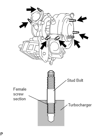
Tighten the 7 stud bolts into the turbocharger until the unthreaded sections of the stud bolts are touching the female screw sections of the turbocharger, as shown in the illustration.
- NOTICE:
- ·
If the bolts are not securely tightened, they may fall out.
·Excessively tightening the bolts may crack the female screw section.
Install a new gasket and the turbocharger with 4 new nuts and 4 spacers.
- Torque:
70 N*m (714 kgf*cm, 52 ft.*lbf)
Connect the connector.
15474
3.INSTALL TURBO OIL OUTLET PIPE
Install the 2 new gaskets and the turbo oil outlet pipe with the 4 bolts.
- Torque:
29 N*m (291 kgf*cm, 21 ft.*lbf)
16027
4.INSTALL NO. 1 TURBO WATER PIPE SUB-ASSEMBLY
Install 4 new gaskets and the No. 1 turbo water pipe with the 2 union bolts.
- Torque:
25 N*m (250 kgf*cm, 18 ft.*lbf)
Install the water by-pass pipe support with the nut.
Tighten the nut until the pipe support edge makes contact with its bracket side pipe support's edge.
15407
5.INSTALL TURBO OIL INLET PIPE
Install 4 new gaskets and the turbo oil inlet pipe with the 2 union bolts and the bolt.
- Torque:
25 N*m (250 kgf*cm, 18 ft.*lbf) for Union Bolt
29 N*m (291 kgf*cm, 21 ft.*lbf) for Bolt
16028
6.INSTALL NO. 2 TURBO WATER PIPE SUB-ASSEMBLY
Install a new O-ring onto the No. 2 turbo water pipe.
Install 2 new gaskets and the No. 2 turbo water pipe sub-assembly with the union bolt and bolt.
- Torque:
25 N*m (250 kgf*cm, 18 ft.*lbf) for Union Bolt
29 N*m (291 kgf*cm, 21 ft.*lbf) for Bolt
17291
7.INSTALL TURBINE OUTLET ELBOW
Install a new gasket and the turbine outlet elbow with the 2 bolts, the 3 nuts and 3 spacers.
- Torque:
29 N*m (291 kgf*cm, 21 ft.*lbf) for Bolt
70 N*m (714 kgf*cm, 52 ft.*lbf) for Nut
17410
8.INSTALL FRONT EXHAUST PIPE ASSEMBLY
Install a new gasket onto the front exhaust pipe.
Install the 2 new gaskets onto the exhaust retarder.
Temporarily install the front exhaust pipe with the 3 nuts and the exhaust retarder with the 4 bolts.
Tighten the clamp bolt.
- Torque:
28 N*m (282 kgf*cm, 20 ft.*lbf)
Tighten the 3 nuts.
- Torque:
62 N*m (632 kgf*cm, 46 ft.*lbf)
Tighten the 4 bolts.
- Torque:
27 N*m (275 kgf*cm, 20 ft.*lbf)
44773D
9.CONNECT SOLENOIDO TO RETARDER HOSE
Connect the solenoid to retarder hose.
17341F
10.CONNECT NO. 1 AIR HOSE
Connect the No. 1 air hose and install the bolt.
- Torque:
18 N*m (184 kgf*cm, 13 ft.*lbf)
25608
11.INSTALL EGR COOLER SUB-ASSEMBLY
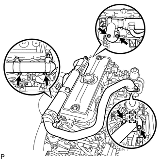
Install the 2 new gaskets, the EGR cooler sub-assembly and harness bracket with the 6 bolts.
- Torque:
69 N*m (699 kgf*cm, 51 ft.*lbf) for Bolt A
55 N*m (561 kgf*cm, 41 ft.*lbf) for Bolt B
Connect the 3 water by-pass hoses.
Connect the water by-pass hose.
17271
12.INSTALL NO. 1 TURBO INSULATOR
Install the No. 1 turbo insulator with the 5 bolts.
- Torque:
29 N*m (291 kgf*cm, 21 ft.*lbf)
17113
13.INSTALL INTAKE PIPE
Install a new gasket and the intake pipe with the 2 nuts and the bolt.
- Torque:
29 N*m (291 kgf*cm, 21 ft.*lbf)
Connect the inlet hose.
16206C
14.INSTALL WATER BY-PASS PIPE SUB-ASSEMBLY
Install the water by-pass pipe with the 6 bolts.
- Torque:
29 N*m (291 kgf*cm, 21 ft.*lbf)
Connect the 2 water by-pass hoses.
15.ADD ENGINE COOLANT
58701A
16.INSTALL FRONT ENGINE SERVICE COVER PANEL SUB-ASSEMBLY
Install the engine service cover front panel sub-assembly with the 3 bolts.
- Torque:
8.0 N*m (82 kgf*cm, 71 in.*lbf)
33504F
17.INSTALL SHIFT LEVER SUB-ASSEMBLY
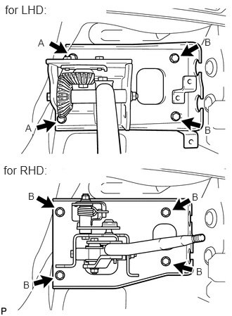
Install the shift lever assembly with the 4 bolts.
- Torque:
7.5 N*m (76 kgf*cm, 66 in.*lbf) for Bolt A
12 N*m (122 kgf*cm, 9 ft.*lbf) for Bolt B
33820B
18.CONNECT TRANSMISSION CONTROL CABLE ASSEMBLY
Install the transmission control cable clamp with the bolt.
- Torque:
12 N*m (122 kgf*cm, 9 ft.*lbf)
Install the shift wire clamp with the nut.
- Torque:
12 N*m (122 kgf*cm, 9 ft.*lbf)
Connect the select cable and shift cable and install the nut and 3 clips.
- Torque:
15 N*m (153 kgf*cm, 11 ft.*lbf)
33531B
19.INSTALL SHIFT AND SELECT LEVER SHAFT DUST BOOT
Install the shift and select lever support with the 4 bolts.
- Torque:
6.0 N*m (61 kgf*cm, 53 in.*lbf)
Install the shift lever knob.
20.INSPECT FOR COOLANT LEAK
21.INSPECT FOR OIL LEAK
22.INSPECT FOR EXHAUST GAS LEAK
53711C
23.INSTALL FRONT FENDER APRON RH
Install the front fender apron RH with the 7 bolts.
- Torque:
7.0 N*m (71 kgf*cm, 62 in.*lbf)
51441D
24.INSTALL NO. 1 ENGINE UNDER COVER (for Metal Type)
Install the No. 1 engine under cover with the 6 bolts.
- Torque:
18 N*m (184 kgf*cm, 13 ft.*lbf)
51441D
25.INSTALL NO. 1 ENGINE UNDER COVER (for Plastic Type)
Install the No. 1 engine under cover with the bolts.
| Made | Bolt |
|---|---|
| for TCAP Made | x8 |
| except TCAP Made | x12 |
- Torque:
18 N*m (184 kgf*cm, 13 ft.*lbf)
51459
26.INSTALL ENGINE SIDE COVER STAY (for TCAP Made)
Install the 2 engine side cover stay with the 8 clips.
58534A
27.INSTALL TRANSMISSION COVER MAT (for Manual Transmission)
58420
28.INSTALL NO. 2 ENGINE SERVICE HOLE COVER ASSEMBLY
58521D
29.INSTALL ENGINE SERVICE HOLE COVER MAT
58734B
30.INSTALL ENGINE SERVICE COVER REAR WEATHERSTRIP
58410
31.INSTALL ENGINE SERVICE HOLE COVER