EXTERIOR SIDE STRIPE TAPE INSTALLATION
PROCEDURE

 1. REPAIR INSTRUCTION
Clean the vehicle body surface.
Using a heat light, heat the vehicle body surface.
- NOTICE:
- ·
Do not touch the heat light and heated parts.
·Touching the heat light may result in burns.
·Touching heated parts for a long time may result in burns.
Wipe off any tape adhesive residue with cleaner.
Installation temperature.
When the ambient temperature is below 15°C (59°F), perform the installation procedure after warming the vehicle body surface (installation surface of the door frame) and tape to between 20 and 30°C (68 and 86°F) using a heat light.
When the ambient temperature is higher than 35°C (95°F), cool the vehicle body surface (installation surface of the door frame) and tape to between 20 and 30°C (68 and 86°F) prior to installation.
- HINT:
- ·
The most appropriate temperature for installing the tape is 25°C (77°F).
·When the temperature is low, the tape turns stiff and falls off easily. When the temperature is high, the tape loses elasticity.
Before installation.
Make sure any dirt on and around the vehicle body surface where the tape will be installed (installation surface of the door frame) is removed, and that the surface is smooth. If the surface is rough or dirt remains when pressing the tape onto the surface, air will be trapped under the tape and result in a poor appearance.
- HINT:
-
Spray water on the shop floor to settle any dust.
Key points for handling the tape.
The tape bends and rolls up easily. Store the tape between flat pieces of cardboard or other similar objects and keep it dry and level.
- NOTICE:
-
Do not bend the tape or leave it in a place with a high temperature.
Key points for the installation of the tape (how to use a squeegee and the installation procedure for corners).
Remove the release paper and apply the tape carefully with your fingers.
Before applying the tape to each corner, heat the tape using a heat light and gradually apply it to avoid wrinkles in the tape and achieve a neat finish.
Check after installation.
After completing the application, check if the tape is applied neatly. If the tape is not applied neatly, apply new tape.
- NOTICE:
-
Do not reuse the tape.
2. ALIGN STRIPE
- HINT:
- ·
Perform the following procedure to determine the installation position when attaching the stripe to the side of the body.
·The illustrations shown are merely examples.
Apply a 24 mm (0.945 in.) wide piece of masking tape (A) to the side panel at the position shown in the illustration.
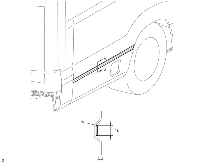
| *a | 24 mm (0.945 in.) | *b | Edge of Curved Surface |
Line up horizontally pieces of masking tape (B) cut into approximately 40 mm (1.57 in.) segments and then draw line (A) and line (B) in the positions shown in the illustration.
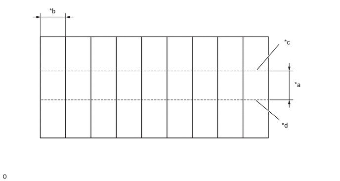
| *a | 24 mm (0.945 in.) | *b | 40 mm (1.57 in.) |
| *c | Line (A) | - | Line (B) |
- HINT:
-
The number of pieces of tape will vary depending on the length of the stripe and the length of the ruler used in step d.
Apply masking tape (B) line (B) aligned with the position shown in the illustration.
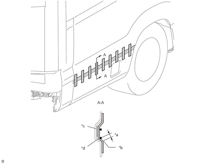
| *a | 2.0 mm (0.0787 in.) | *b | Edge of Curved Surface |
| *c | Line (A) | *d | Line (B) |
- NOTICE:
-
The tolerance for applying masking tape (B) is +/-1 mm (0.0394 in.).
- HINT:
-
Apply it aligned with the length of the ruler.
Place the ruler on masking tape (B) line (A) and then draw a line on masking tape (A).
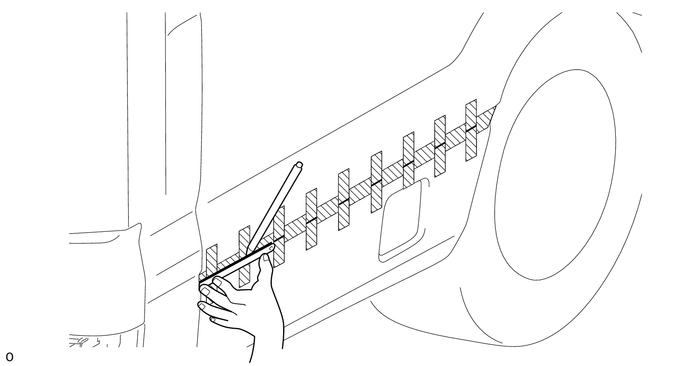
Peel masking tape (B) and then draw a line where the tape was peeled.
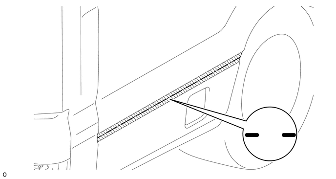
Apply a 24 mm (0.945 in.) wide piece of masking tape (C) aligned with the line drawn on masking tape (A).
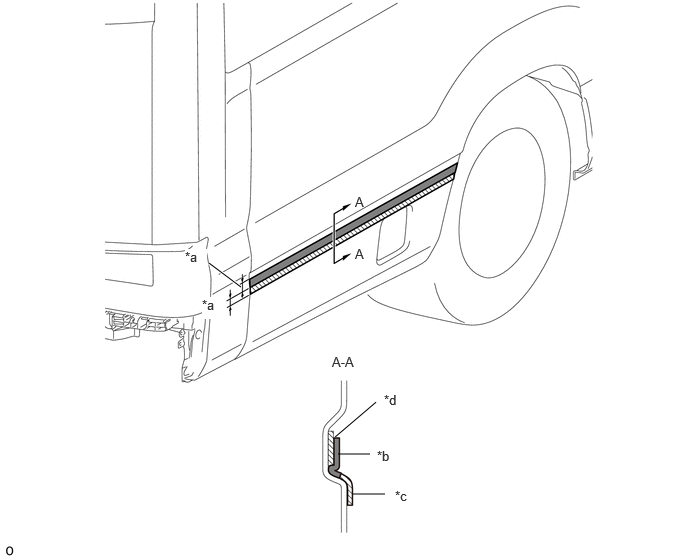
| *a | 24 mm (0.945 in.) | *b | Masking Tape (C) |
| *c | Masking Tape (D) | *d | Line Drawn on Masking Tape (A) |
Apply a 24 mm (0.945 in.) wide piece of masking tape (D) to the lower side of masking tape (C).
Remove the masking tape (C).
Align the edges of the stripe application tape with the line drawn on masking tape (A) and then temporarily align the stripe.
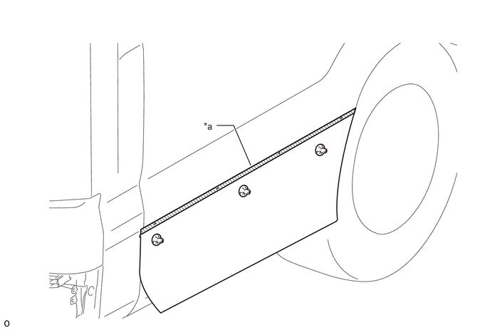
| *a | Application Tape | - | - |
- HINT:
-
Attach the stripe on masking tape (C) to prevent pressing it completely into place.
3. ATTACH STRIPE (FLUT SURFACE)
- HINT:
- ·
This procedure is used to press the stripe into place on the flat surface of the body panel.
·The illustrations shown are merely examples.
Peel the peeling paper approximately 30 mm (1.18 in.) from the upper side of the vehicle and then temporarily press it into place using a squeegee.
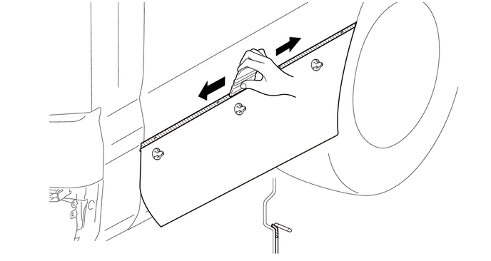
- NOTICE:
-
Be careful not to press it completely into place.
Peel the peeling paper approximately 30 mm (1.18 in.) and then press the tape into place by moving a squeegee from the center of the tape outward in a fan-shaped pattern.
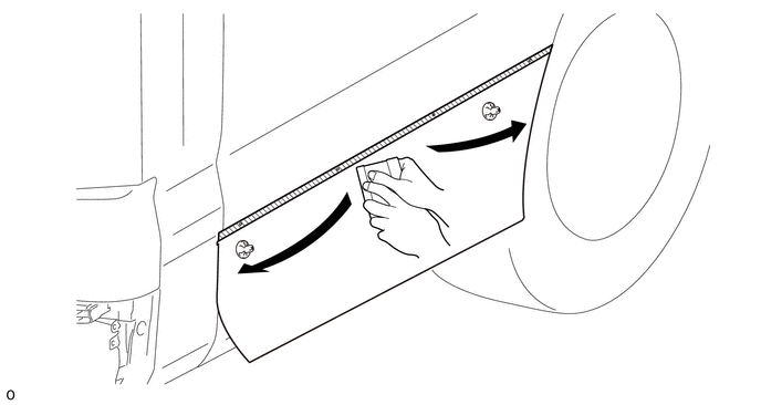
Repeat step b and press the stripe into place up to the lower edge of the body panel.
4. ATTACH STRIPE (UPPER EDGE)
- HINT:
- ·
This procedure is used to press the upper edge of the stripe into place on the body panel.
·The illustrations shown are merely examples.
After attaching the stripe up to the lower edge of the body, peel the application tape back and then remove masking tape (A) and (D).
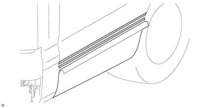
Move a squeegee from the center of the stripe toward both ends of the stripe and then press the tape into place around the edge of the curve.
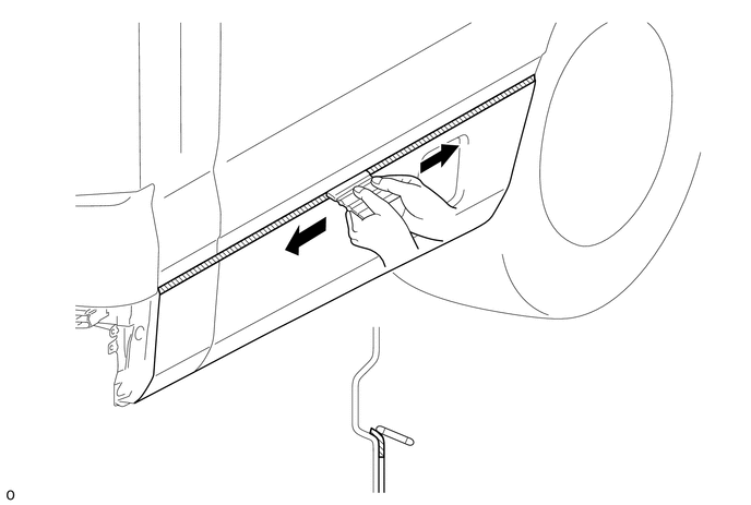
Move the squeegee little by little up and down from the center of the stripe as shown in the illustration, and then press the stripe into place on both ends in turn.
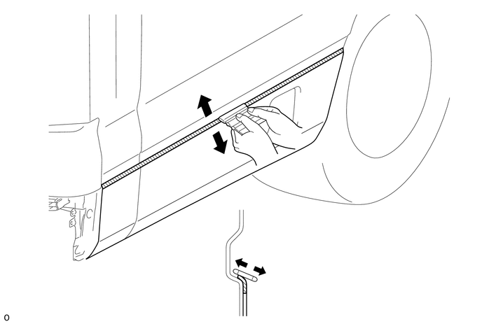
75994
5.INSTALL NO. 2 QUARTER STRIPE LH
- HINT:
-
When installing the No. 2 quarter stripe LH, heat the vehicle body and No. 2 quarter stripe LH using a heat light.
| Item | Temperature |
|---|---|
| Vehicle Body | 40 to 60 °C (104 to 140 °F) |
| No. 2 Quarter Stripe LH | 20 to 30 °C (68 to 86 °F) |
- NOTICE:
- ·
Do not touch the heat light and heated parts.
·Touching the heat light may result in burns.
·Touching heated parts for a long time may result in burns.
Align the stripe.
Click hereVehicle Interior>EXTERIOR>SIDE STRIPE TAPE>INSTALLATION
Align a new No. 2 quarter stripe LH in the horizontal direction in the position shown in the illustration.
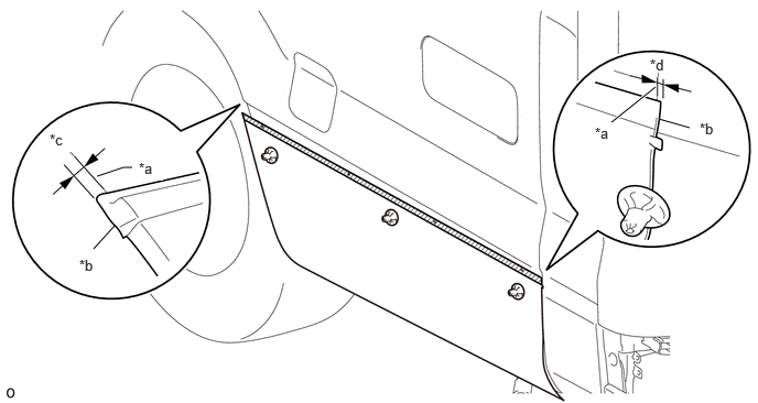
| *a | Queter Panel End Face | *b | No. 2 Quarter Stripe LH End Face |
| *c | 3.0 mm (0.118 in.) | *d | 3.0 mm (0.118 in.) |
Attach the stripe (flat surface).
Click hereVehicle Interior>EXTERIOR>SIDE STRIPE TAPE>INSTALLATION
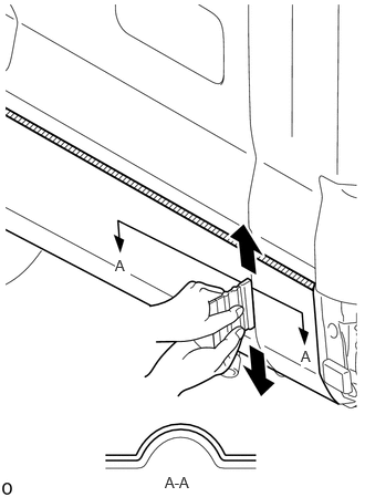
Using a squeegee, press the No. 2 quarter stripe LH into place from the center of the body sealer upward and downward.
- NOTICE:
-
Not pressing it into place from the sealer center will cause air bubbles or lifting.
Attach the stripe (upper edge).
Click hereVehicle Interior>EXTERIOR>SIDE STRIPE TAPE>INSTALLATION
Remove the application tape.
Attach the rear slits:
Attach the No. 2 quarter stripe LH end slits in the order shown in the illustration.
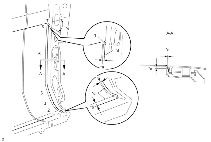
| *a | 3.0 mm (0.118 in.) | *b | 10 mm (0.394 in.) |
| *c | 0.5 mm (0.0197 in.) | *d | Edge of Curved Surface |
| *e | 30° | *f | Slit (A) |
- HINT:
-
Attach slit (A) pulled 30° toward the lower side of the vehicle.
Attach the front slits:
Attach the No. 2 quarter stripe LH end slits in the order shown in the illustration.
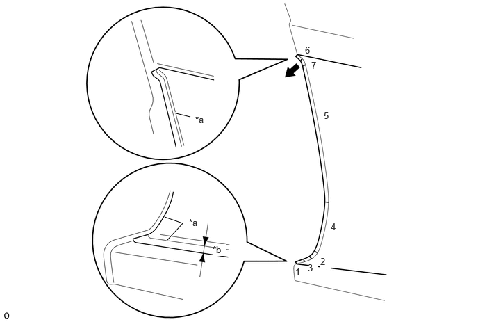
| *a | Edge of Curved Surface | *b | 10 mm (0.394 in.) |
The last slit to attach must be attached by pulling it lightly in the direction of the arrow shown in the illustration.
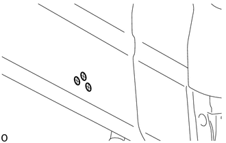
Cut a cross-shaped notch in the side marker installation hole.
75993A
6.INSTALL REAR QUARTER STRIPE RH
- HINT:
-
When installing the rear quarter stripe RH, heat the vehicle body and rear quarter stripe RH using a heat light.
| Item | Temperature |
|---|---|
| Vehicle Body | 40 to 60 °C (104 to 140 °F) |
| Rear Quarter Stripe RH | 20 to 30 °C (68 to 86 °F) |
- NOTICE:
- ·
Do not touch the heat light and heated parts.
·Touching the heat light may result in burns.
·Touching heated parts for a long time may result in burns.
Align the stripe.
Click hereVehicle Interior>EXTERIOR>SIDE STRIPE TAPE>INSTALLATION
Align a new rear quarter stripe RH in the horizontal direction in the position shown in the illustration.
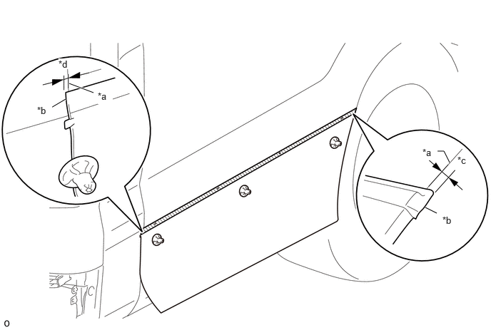
| *a | Quarter Panel End Face | *b | Rear Quarter Stripe RH End Face |
| *c | 3.0 mm (0.118 in.) | *d | 3.0 mm (0.118 in.) |
Attach the stripe (flat surface).
Click hereVehicle Interior>EXTERIOR>SIDE STRIPE TAPE>INSTALLATION
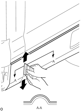
Using a squeegee, press the rear quarter stripe RH into place from the center of the body sealer upward and downward.
- NOTICE:
-
Not pressing it into place from the sealer center will cause air bubbles or lifting.
Attach the stripe (upper edge).
Click hereVehicle Interior>EXTERIOR>SIDE STRIPE TAPE>INSTALLATION
Remove the application tape.
Attach the rear slits:
Attach the rear quarter stripe RH end slits in the order shown in the illustration.
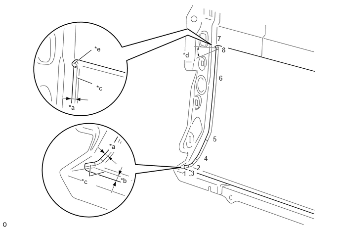
| *a | 3.0 mm (0.118 in.) | *b | 10 mm (0.394 in.) |
| *c | Edge of Curved Surface | *d | 30° |
| *e | Slit (A) | - | - |
- HINT:
-
Attach slit (A) pulled 30° toward the lower side of the vehicle.
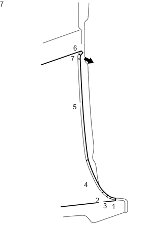
Attach the front slits:
Attach the rear quarter stripe RH end slits in the order shown in the illustration.
The last slit to attach must be attached by pulling it lightly in the direction of the arrow shown in the illustration.
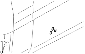
Cut a cross-shaped notch in the side marker installation hole.
52159
7.INSTALL REAR BUMPER COVER
75986A
8.INSTALL SIDE PANEL STRIPE LH
- HINT:
-
When installing the side panel stripe LH, heat the vehicle body and side panel stripe LH using a heat light.
| Item | Temperature |
|---|---|
| Vehicle Body | 40 to 60 °C (104 to 140 °F) |
| Side Panel Stripe LH | 20 to 30 °C (68 to 86 °F) |
- NOTICE:
- ·
Do not touch the heat light and heated parts.
·Touching the heat light may result in burns.
·Touching heated parts for a long time may result in burns.
Align the stripe.
Click hereVehicle Interior>EXTERIOR>SIDE STRIPE TAPE>INSTALLATION
Align a new side panel stripe LH in the horizontal direction in the position shown in the illustration.
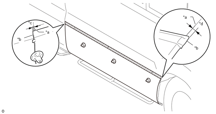
| *a | Side Panel End Face | *b | Side Panel Stripe LH End Face |
| *c | 3.0 mm (0.118 in.) | *d | 3.0 mm (0.118 in.) |
Attach the stripe (flat surface).
Click hereVehicle Interior>EXTERIOR>SIDE STRIPE TAPE>INSTALLATION
Attach the stripe (upper edge).
Click hereVehicle Interior>EXTERIOR>SIDE STRIPE TAPE>INSTALLATION
Remove the application tape.
Attach the rear slits:
Attach the side panel stripe LH end slits in the order shown in the illustration.
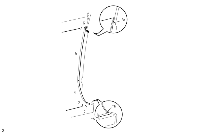
| *a | Edge of Curved Surface | *b | 10 mm (0.394 in.) |
The last slit to attach must be attached by pulling it lightly in the direction of the arrow shown in the illustration.
Attach the front slits (for Glide Type):
Attach the side panel stripe LH end slits in the order shown in the illustration.
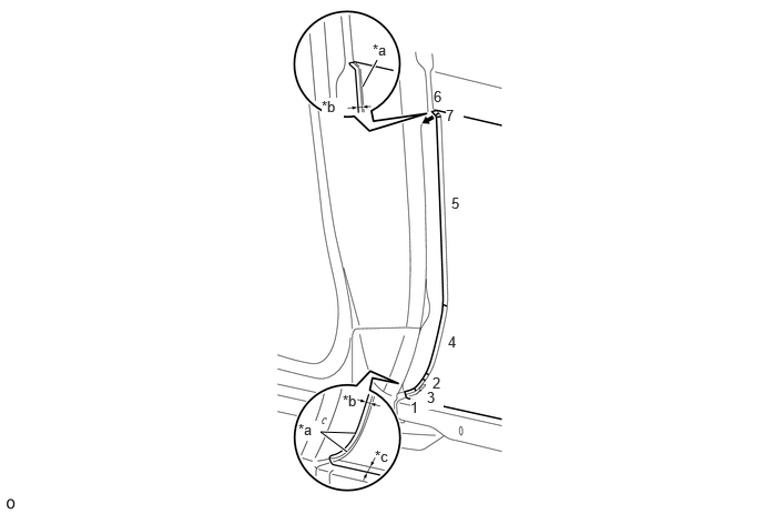
| *a | Edge of Curved Surface | *b | 3.0 mm (0.118 in.) |
| *c | 10 mm (0.394 in.) | - | - |
The last slit to attach must be attached by pulling it lightly in the direction of the arrow shown in the illustration.
Attach the front slits (for Folding Type):
Attach the side panel stripe LH end slits in the order shown in the illustration.
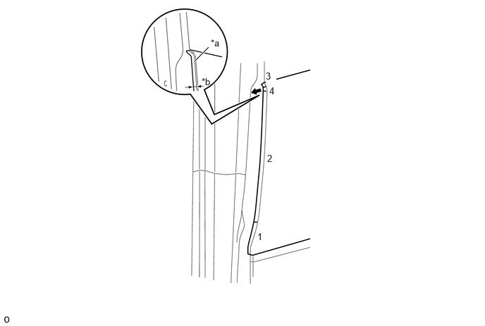
| *a | Edge of Curved Surface | *b | 3.0 mm (0.118 in.) |
The last slit to attach must be attached by pulling it lightly in the direction of the arrow shown in the illustration.
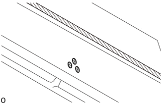
Cut a cross-shaped notch in the side marker installation hole.
75986A
9.INSTALL SIDE PANEL STRIPE LH (for Standard Body)
- HINT:
-
Use the same procedure as for the side panel stripe LH.
75985A
10.INSTALL SIDE PANEL STRIPE RH
- HINT:
-
When installing the side panel stripe RH, heat the vehicle body and side panel stripe RH using a heat light.
| Item | Temperature |
|---|---|
| Vehicle Body | 40 to 60 °C (104 to 140 °F) |
| Side Panel Stripe RH | 20 to 30 °C (68 to 86 °F) |
- NOTICE:
- ·
Do not touch the heat light and heated parts.
·Touching the heat light may result in burns.
·Touching heated parts for a long time may result in burns.
Align the stripe.
Click hereVehicle Interior>EXTERIOR>SIDE STRIPE TAPE>INSTALLATION
Align a new side panel stripe RH in the horizontal direction in the position shown in the illustration.
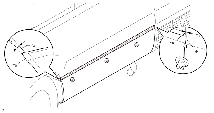
| *a | Side Panel End Face | *b | Side Panel Stripe RH End Face |
| *c | 3.0 mm (0.118 in.) | *d | 3.0 mm (0.118 in.) |
Attach the stripe (flat surface).
Click hereVehicle Interior>EXTERIOR>SIDE STRIPE TAPE>INSTALLATION
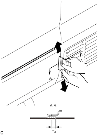
Using a squeegee, press the side panel stripe RH into place from the center of the body sealer upward and downward.
- NOTICE:
-
Not pressing it into place from the sealer center will cause air bubbles or lifting.
| *a | 3.0 mm (0.118 in.) |
Attach the stripe (upper edge).
Click hereVehicle Interior>EXTERIOR>SIDE STRIPE TAPE>INSTALLATION
Remove the application tape.
Attach the rear slits
Attach the side panel stripe RH end slits in the order shown in the illustration.
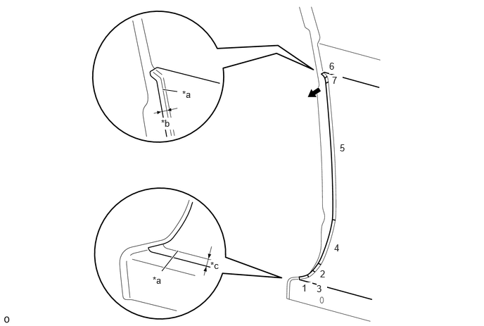
| *a | R END | *b | 3.0 mm (0.118 in.) |
| *c | 10 mm (0.394 in.) | - | - |
The last slit to attach must be attached by pulling it lightly in the direction of the arrow shown in the illustration.
75985A
11.INSTALL SIDE PANEL STRIPE RH (for Standard Body)
- HINT:
-
Use the same procedure as for the side panel stripe RH.
75982D
12.INSTALL FENDER STRIPE LH (for Rear Side)
- HINT:
-
When installing the fender stripe LH, heat the vehicle body and fender stripe LH using a heat light.
| Item | Temperature |
|---|---|
| Vehicle Body | 40 to 60 °C (104 to 140 °F) |
| Fender Stripe LH | 20 to 30 °C (68 to 86 °F) |
- NOTICE:
- ·
Do not touch the heat light and heated parts.
·Touching the heat light may result in burns.
·Touching heated parts for a long time may result in burns.
for Front Side:
Peel the peeling paper little by little from the upper side and then attach a new fender stripe LH aligned with the shape of the side panel.
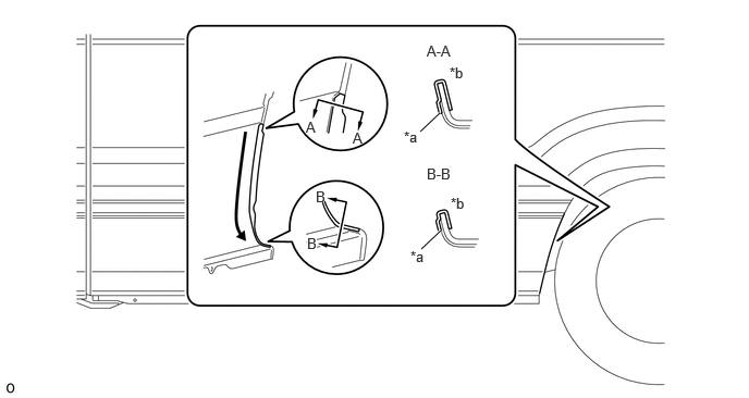
| *a | Edge of Curved Surface | *b | Wrap |
Remove the application tape.
for Rear Side:
Peel the peeling paper little by little from the upper side and then attach a new fender stripe LH aligned with the shape of the side panel.
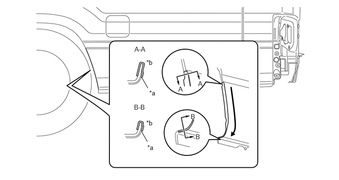
| *a | Edge of Curved Surface | *b | Wrap |
Remove the application tape.
75992C
13.INSTALL QUARTER STRIPE LH
Peel the peeling paper little by little from the upper side and then attach a new quarter stripe LH aligned with the shape of the side panel.
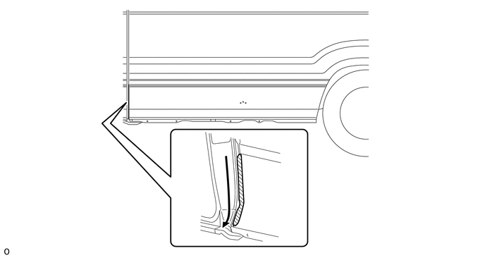
Remove the application tape.
75981B
14.INSTALL FENDER STRIPE RH (for Rear Side)
- HINT:
-
When installing the fender stripe RH, heat the vehicle body and fender stripe RH using a heat light.
| Item | Temperature |
|---|---|
| Vehicle Body | 40 to 60 °C (104 to 140 °F) |
| Fender Stripe RH | 20 to 30 °C (68 to 86 °F) |
- NOTICE:
- ·
Do not touch the heat light and heated parts.
·Touching the heat light may result in burns.
·Touching heated parts for a long time may result in burns.
for Front Side:
Peel the peeling paper little by little from the upper side and then attach a new fender stripe RH aligned with the shape of the side panel.
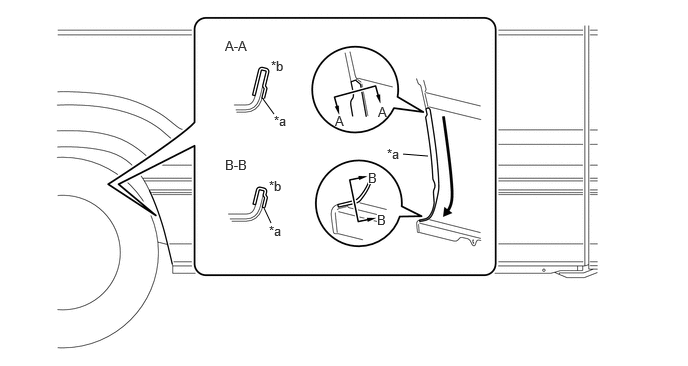
| *a | Edge of Curved Surface | *b | Wrap |
Remove the application tape.
for Rear Side:
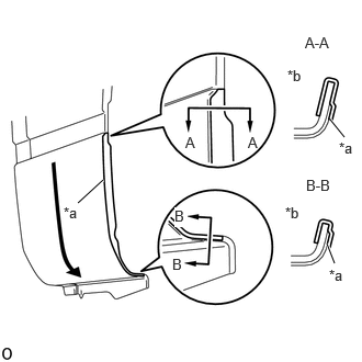
Peel the peeling paper little by little from the upper side and then attach a new fender stripe RH aligned with the shape of the side panel.
| *a | Edge of Curved Surface |
| *b | Wrap |
Remove the application tape.
75993A
15.INSTALL REAR QUARTER STRIPE RH
- HINT:
-
When installing the rear quarter stripe RH, heat the vehicle body and rear quarter stripe RH using a heat light.
| Item | Temperature |
|---|---|
| Vehicle Body | 40 to 60 °C (104 to 140 °F) |
| Rear Quarter Stripe RH | 20 to 30 °C (68 to 86 °F) |
- NOTICE:
- ·
Do not touch the heat light and heated parts.
·Touching the heat light may result in burns.
·Touching heated parts for a long time may result in burns.
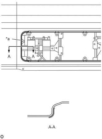
Apply primer to the cooler condenser cover installation area.
| *a | Primer |
Align the stripe.
Click hereVehicle Interior>EXTERIOR>SIDE STRIPE TAPE>INSTALLATION
Align a new rear quarter stripe RH in the horizontal direction in the position shown in the illustration.
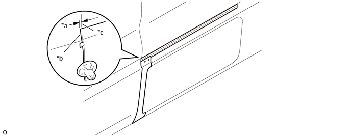
| *a | 3.0 mm (0.118 in.) | *b | Rear Quarter Stripe RH End Face |
| *c | Quarter Panel End Face | - | - |
Using a squeegee, press the body flat surface into place.
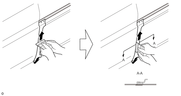
Using a squeegee, press the Rear quarter stripe RH into place from the center of the body sealer upward and downward.
- NOTICE:
-
Not pressing it into place from the sealer center will cause air bubbles or lifting
Attach the stripe (upper edge).
Click hereVehicle Interior>EXTERIOR>SIDE STRIPE TAPE>INSTALLATION
Remove the application tape.
Using a squeegee, fold everything except the lower curve and then press it into place.
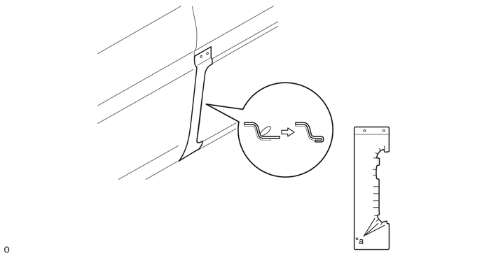
| *a | Vehicle Lower Curve | - | - |
- NOTICE:
-
The lower curve must be folded when installing the lower quarter stripe RH.
75996F
16.INSTALL UPPER QUARTER STRIPE RH
- HINT:
-
When installing the upper quarter stripe RH, heat the vehicle body and upper quarter stripe RH using a heat light.
| Item | Temperature |
|---|---|
| Vehicle Body | 40 to 60 °C (104 to 140 °F) |
| Upper Quarter Stripe RH | 20 to 30 °C (68 to 86 °F) |
- NOTICE:
- ·
Do not touch the heat light and heated parts.
·Touching the heat light may result in burns.
·Touching heated parts for a long time may result in burns.
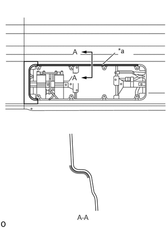
Apply primer to the cooler condenser cover installation area.
| *a | Primer |
Align the edge of the application tape with the line on the masking tape.
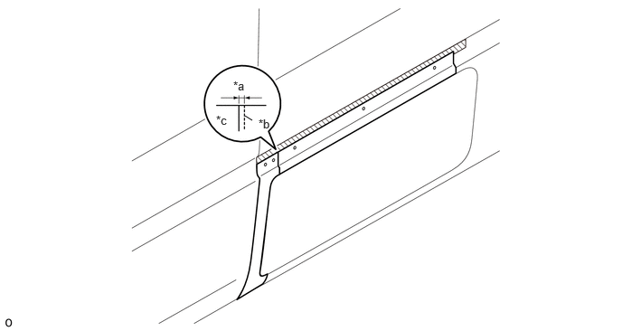
| *a | 5.0 mm | *b | Rear Quarter Stripe RH End Face |
| *c | Overlap Reference Value | - | - |
Align a new upper quarter stripe RH in the horizontal direction in the position shown in the illustration.
- HINT:
-
Attach to a position overlapping the rear quarter stripe RH that was previously attached by 5.0 mm (0.197 in.).
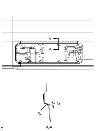
Using a squeegee, attach the upper quarter stripe RH to the position shown in the illustration.
| *a | 3.0 mm (0.118in.) |
| *b | Edge of Curved Surface |
Move the squeegee to press the body sealer into place as shown in the illustration.
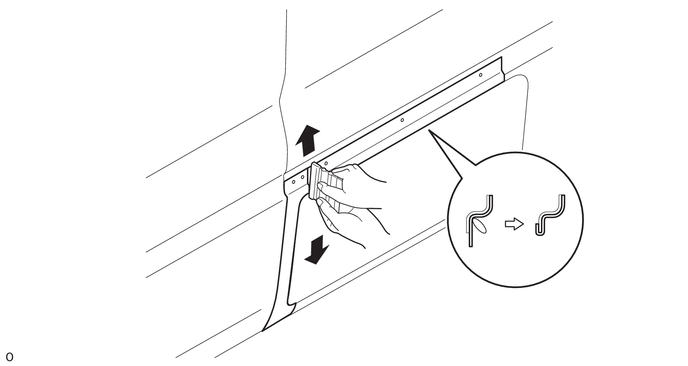
Remove the application tape.
75973F
17.INSTALL FRONT SIDE PANEL STRIPE RH
- HINT:
-
When installing the front side panel stripe RH, heat the vehicle body and front side panel stripe RH using a heat light.
| Item | Temperature |
|---|---|
| Vehicle Body | 40 to 60 °C (104 to 140 °F) |
| Front Side Panel Stripe RH | 20 to 30 °C (68 to 86 °F) |
- NOTICE:
- ·
Do not touch the heat light and heated parts.
·Touching the heat light may result in burns.
·Touching heated parts for a long time may result in burns.
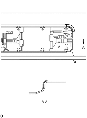
Apply primer to the cooler condenser cover installation area.
| *a | Primer |
Align the stripe.
Click hereVehicle Interior>EXTERIOR>SIDE STRIPE TAPE>INSTALLATION
Align a new front side stripe RH in the horizontal direction in the position shown in the illustration.
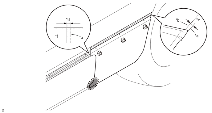
| *a | Front Side Stripe RH End Face | *b | Side Panel End Face |
| *c | 3.0 mm (0.118 in.) | *d | 5.0 mm (0.197 in.) |
| *e | Upper Quarter Stripe RH End Face | *f | Overlap Reference Value |

|
Leave Peeling Paper Here | - | - |
- HINT:
-
Attach to a position overlapping the upper quarter stripe RH that was previously attached by 5 mm (0.197 in.).
Attach the stripe (flat surface).
Click hereVehicle Interior>EXTERIOR>SIDE STRIPE TAPE>INSTALLATION
- NOTICE:
-
Leave the peeling paper in the position shown in the illustration. Do not peel it.
Attach the front slits:
Attach the front side stripe RH end slits in the order shown in the illustration.
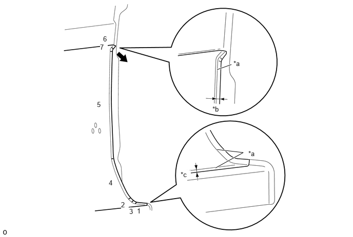
| *a | Edge of Curved Surface | *b | 3.0 mm (0.118 in.) |
| *c | 10 mm (0.394 in.) | - | - |
The last slit to attach must be attached by pulling it lightly in the direction of the arrow shown in the illustration.
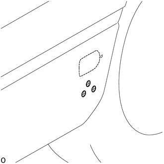
Cut a cross-shaped notch in the side turn signal light installation hole.
Cut a cross-shaped notch in the side marker installation hole.
Move the squeegee to press the body sealer into place as shown in the illustration.
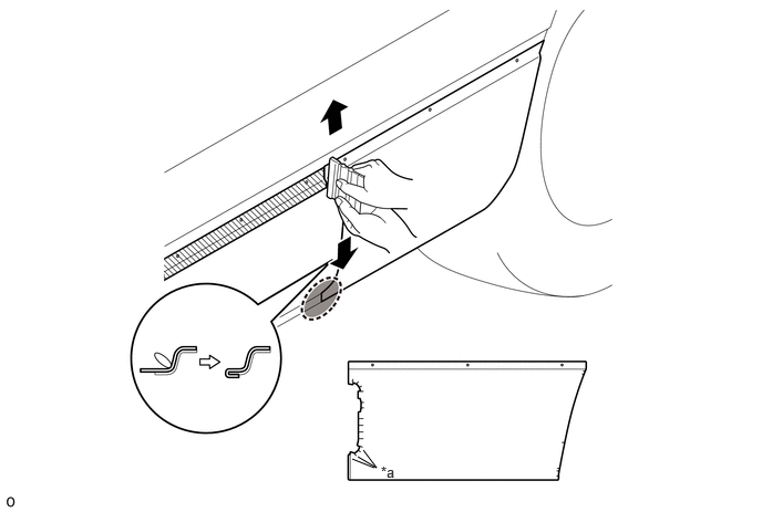
| *a | Vehicle Lower Curve | - | - |
|
|
Leave Peeling Paper Here | - | - |
Leave a part of the peeling paper in place, then fold and press into place everywhere other than the curve on the lower side of the front side panel stripe RH.
- NOTICE:
-
Leave the peeling paper in the position shown in the illustration. Do not peel it.
75991F
18.INSTALL LOWER QUARTER STRIPE RH
- HINT:
-
When installing the lower quarter stripe RH, heat the vehicle body and lower quarter stripe RH using a heat light.
| Item | Temperature |
|---|---|
| Vehicle Body | 40 to 60 °C (104 to 140 °F) |
| Lower Quarter Stripe RH | 20 to 30 °C (68 to 86 °F) |
- NOTICE:
- ·
Do not touch the heat light and heated parts.
·Touching the heat light may result in burns.
·Touching heated parts for a long time may result in burns.
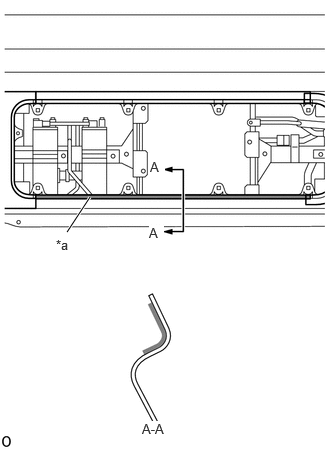
Apply primer to the cooler condenser cover installation area.
| *a | Primer |
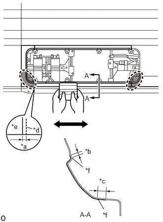
Peel the front side panel stripe RH back and then temporarily align a new lower quarter stripe RH in the position shown in the illustration.
| *a | 5.0 mm (0.197 in.) |
| *b | 3.0 mm (0.118 in.) |
| *c | 10 mm (0.394 in.) |
| *d | Upper Quarter Stripe RH End Face |
| *e | Overlap Reference Value |
| *f | Edge of Curved Surface |
|
|
Front Side Panel Stripe RH and Upper Quarter Stripe RH Lower Curve |
Attach the lower quarter stripe RH to a position overlapping the upper quarter stripe RH that was previously attached by 5 mm (0.197 in.).
Using a squeegee, press the lower quarter stripe RH.
Fold and press into place the curve on the lower side of the front side panel stripe RH and upper quarter stripe RH.
Remove the application tape.
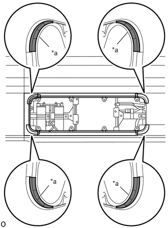
Apply primer to the 4 curves.
| *a | Primer |
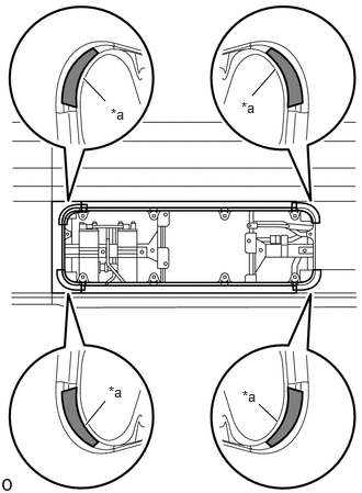
Attach patches to the 4 curves.
| *a | Patch |
75974E
19.INSTALL FRONT SIDE PANEL STRIPE LH
- HINT:
-
When installing the front side panel stripe LH, heat the vehicle body and front side panel stripe LH using a heat light.
| Item | Temperature |
|---|---|
| Vehicle Body | 40 to 60 °C (104 to 140 °F) |
| Front Side Panel Stripe LH | 20 to 30 °C (68 to 86 °F) |
- NOTICE:
- ·
Do not touch the heat light and heated parts.
·Touching the heat light may result in burns.
·Touching heated parts for a long time may result in burns.
Align the stripe.
Click hereVehicle Interior>EXTERIOR>SIDE STRIPE TAPE>INSTALLATION
Align a new front side panel stripe LH in the horizontal direction in the position shown in the illustration.
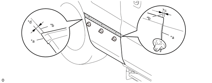
| *a | Front Side Panel Stripe LH End Face | *b | Side Panel End Face |
| *c | 3.0 mm (0.118 in.) | *d | 3.0 mm (0.118 in.) |
Attach the stripe (flat surface).
Click hereVehicle Interior>EXTERIOR>SIDE STRIPE TAPE>INSTALLATION
Attach the stripe (upper edge).
Click hereVehicle Interior>EXTERIOR>SIDE STRIPE TAPE>INSTALLATION
Remove the application tape.
for Glide Type:
Attach the front side panel stripe LH end slits in the order shown in the illustration.
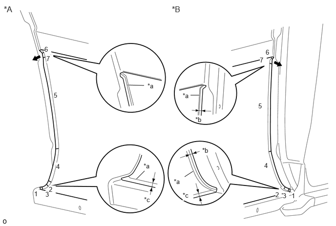
| *A | Front Slits | *B | Rear Slits |
| *a | Edge of Curved Surface | *b | 3.0 mm (0.118 in.) |
| *c | 10 mm (0.394 in.)10 mm | - | - |
The last slit to attach must be attached by pulling it lightly in the direction of the arrow shown in the illustration.
for Folding Type:
Attach the front side panel stripe LH end slits in the order shown in the illustration.
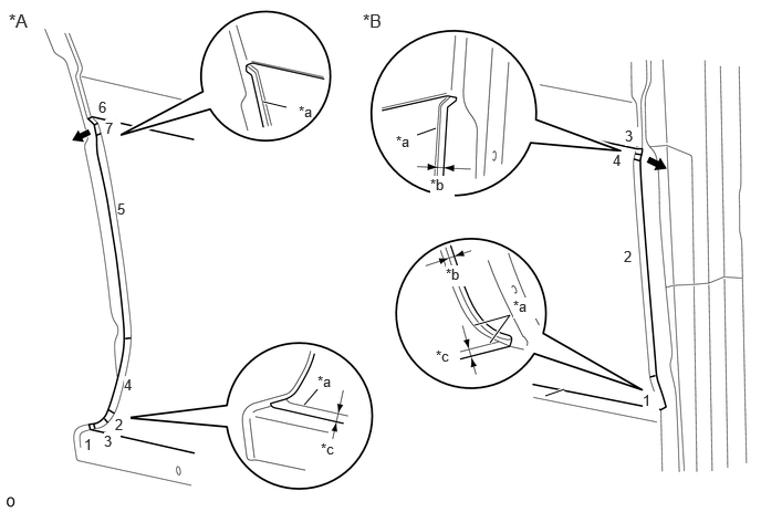
| *A | Front Slits | *B | Rear Slits |
| *a | Edge of Curved Surface | *b | 3.0 mm (0.118 in.) |
| *c | 10 mm (0.394 in.) | - | - |
The last slit to attach must be attached by pulling it lightly in the direction of the arrow shown in the illustration.
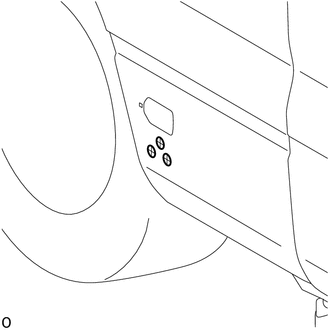
Cut a cross-shaped notch in the side marker installation hole.
59401
20.INSTALL COOLER CONDENSER COVER SUB-ASSEMBLY
81590
21.INSTALL REFLEX SIDE REFLECTOR ASSEMBLY LH
81740
22.INSTALL SIDE TURN SIGNAL LIGHT ASSEMBLY LH
75992D
23.INSTALL FRONT QUARTER STRIPE LH
Peel the peeling paper little by little from the upper side and then attach a new front quarter stripe LH aligned with the shape of the fender panel.
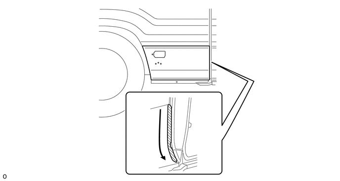
Remove the application tape.
75981B
24.INSTALL FENDER STRIPE RH (for Front Side)
- HINT:
-
When installing the fender stripe RH, heat the vehicle body and fender stripe RH using a heat light.
| Item | Temperature |
|---|---|
| Vehicle Body | 40 to 60 °C (104 to 140 °F) |
| Fender Stripe RH | 20 to 30 °C (68 to 86 °F) |
- NOTICE:
- ·
Do not touch the heat light and heated parts.
·Touching the heat light may result in burns.
·Touching heated parts for a long time may result in burns.
Peel the peeling paper little by little from the upper side and then attach a new fender stripe RH aligned with the shape of the fender panel.
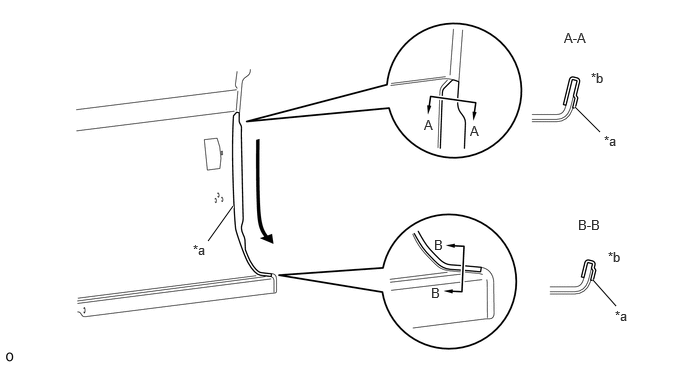
| *a | Edge of Curved Surface | *b | Wrap |
Remove the application tape.
75982B
25.INSTALL FENDER STRIPE LH
- HINT:
-
When installing the fender stripe LH, heat the vehicle body and fender stripe LH using a heat light.
| Item | Temperature |
|---|---|
| Vehicle Body | 40 to 60 °C (104 to 140 °F) |
| Fender Stripe LH | 20 to 30 °C (68 to 86 °F) |
- NOTICE:
- ·
Do not touch the heat light and heated parts.
·Touching the heat light may result in burns.
·Touching heated parts for a long time may result in burns.
Align the stripe.
Click hereVehicle Interior>EXTERIOR>SIDE STRIPE TAPE>INSTALLATION
Align a new fender stripe LH in the horizontal direction in the position shown in the illustration.
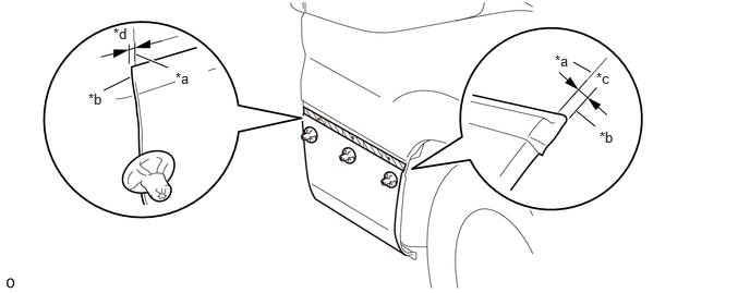
| *a | Fender Panel End Face | *b | Fender Stripe LH End Face |
| *c | 5.0 mm (0.197 in.) | *d | 3.0 mm (0.118 in.) |
Attach the stripe (flat surface).
Click hereVehicle Interior>EXTERIOR>SIDE STRIPE TAPE>INSTALLATION
Attach the stripe (upper edge).
Click hereVehicle Interior>EXTERIOR>SIDE STRIPE TAPE>INSTALLATION
Remove the application tape.
Attach the front slits:
Attach the fender stripe LH end slits in the order shown in the illustration.
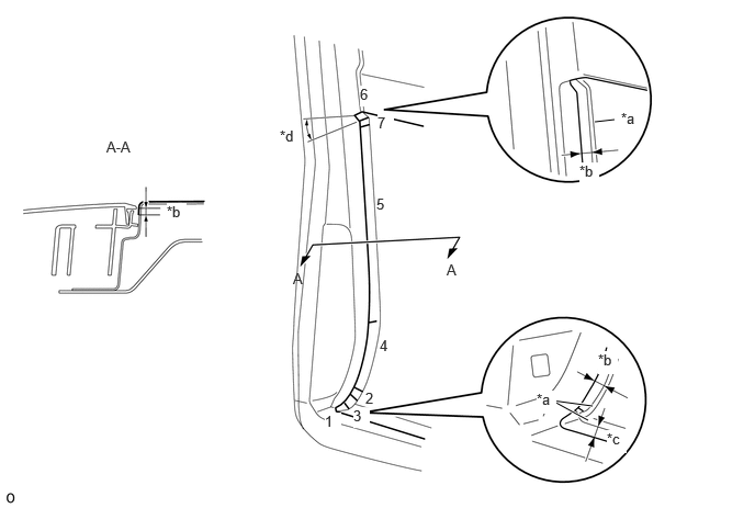
| *a | Edge of Curved Surface | *b | 5.0 mm (0.197 in.) |
| *c | 10 mm (0.394 in.) | *d | 30° |
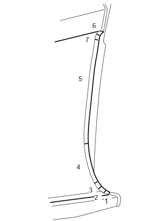
Attach the rear slits:
Attach the fender stripe LH end slits in the order shown in the illustration.
75982D
26.INSTALL FENDER STRIPE LH (for Front Side)
- HINT:
-
When installing the fender stripe LH, heat the vehicle body and fender stripe LH using a heat light.
| Item | Temperature |
|---|---|
| Vehicle Body | 40 to 60 °C (104 to 140 °F) |
| Fender Stripe LH | 20 to 30 °C (68 to 86 °F) |
- NOTICE:
- ·
Do not touch the heat light and heated parts.
·Touching the heat light may result in burns.
·Touching heated parts for a long time may result in burns.
for front side:
Peel the peeling paper little by little from the upper side and then attach a new fender stripe LH aligned with the shape of the fender panel.
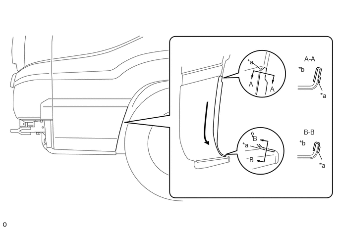
| *a | Edge of Curved Surface | *b | Wrap |
Remove the application tape.
for rear side:
Peel the peeling paper little by little from the upper side and then attach a new fender stripe LH aligned with the shape of the fender panel.
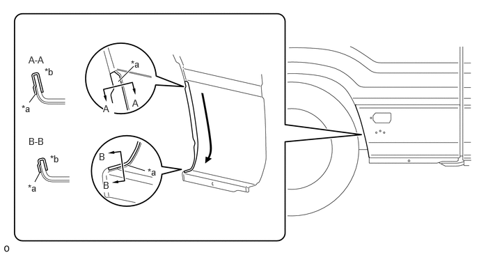
| *a | Edge of Curved Surface | *b | Wrap |
Remove the application tape.
75985
27.INSTALL FRONT DOOR STRIPE RH
- HINT:
-
When installing the front door stripe RH, heat the vehicle body and front door stripe RH using a heat light.
| Item | Temperature |
|---|---|
| Vehicle Body | 40 to 60 °C (104 to 140 °F) |
| Front Door Stripe RH | 20 to 30 °C (68 to 86 °F) |
- NOTICE:
- ·
Do not touch the heat light and heated parts.
·Touching the heat light may result in burns.
·Touching heated parts for a long time may result in burns.
Apply primer to the positions shown in the illustration.
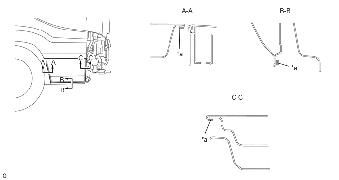
| *a | Primer | - | - |
Align the stripe.
Click hereVehicle Interior>EXTERIOR>SIDE STRIPE TAPE>INSTALLATION
Align a new front door stripe RH in the horizontal direction in the position shown in the illustration.
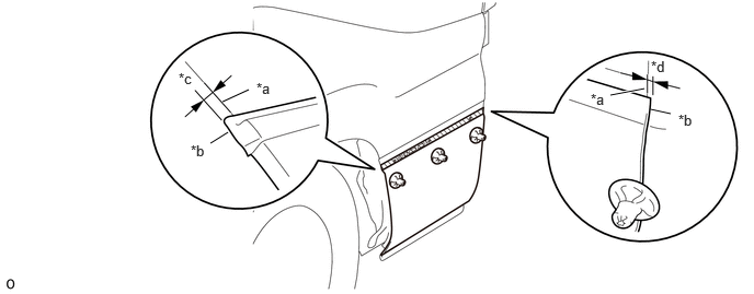
| *a | Door Panel End Face | *b | Front Door Stripe RH End Face |
| *c | 3.0 mm (0.118 in.) | *d | 3.0 mm (0.118 in.) |
Attach the stripe (flat surface).
Click hereVehicle Interior>EXTERIOR>SIDE STRIPE TAPE>INSTALLATION
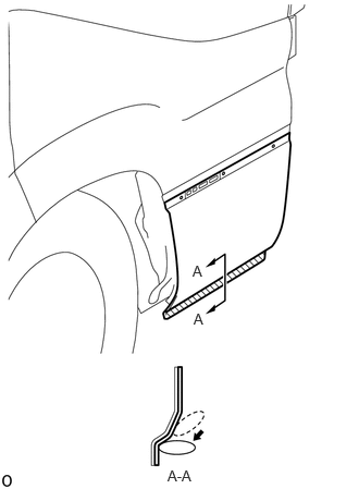
Using a squeegee, press the front door stripe RH into place on the door panel.
Remove the application tape.
Attach the front slits:
Attach the front dooe stripe RH end slits in the order shown in the illustration.
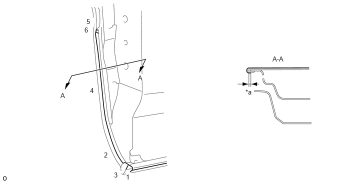
| *a | 3.0 mm (0.118 in.) | - | - |
Attach the rear slits:
Attach the front dooe stripe RH end slits in the order shown in the illustration.
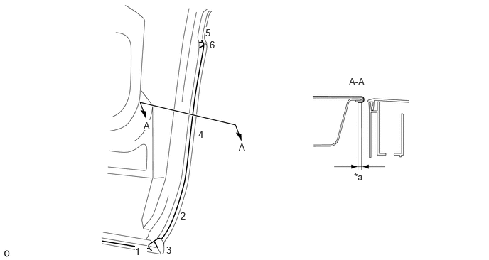
| *a | 3.0 mm (0.118 in.) | - | - |
Fold the lower side of the front door stripe RH and press it into place.
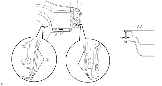
| *a | 3.0 mm | *b | Tab Tape |
Install new 4 tab tapes.
52119A
28.INSTALL FRONT BUMPER COVER (w/o Snorkel Air Cleaner)
52119A
29.INSTALL FRONT BUMPER COVER (w/ Snorkel Air Cleaner)