INTRODUCTION WHEN REMOVING,INSTALLING,REPAIRING OR REPLACING PARTS WHEEL ALIGNMENT STANDARD
MEASURE VEHICLE HEIGHT
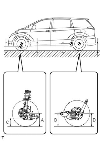
- NOTICE:
-
Before inspecting the wheel alignment, adjust the vehicle height to the specification.
Press down on the vehicle several times to stabilize the suspension, and measure the vehicle height.
Measure the front vehicle height.
Measure the distance from the ground to the center of the No. 1 lower suspension arm front mounting bolt.
Measure the rear vehicle height.
Measure the distance from the ground to the center of the body side axle beam mounting bolt.
- Standard vehicle height (unloaded vehicle):
Front C - A Rear D - B 93 mm (3.66 in.) -37 mm (-1.46 in.)
- HINT:
-
If the vehicle height is not as specified, press down on the vehicle several times to stabilize the suspension. Then measure the vehicle height again.
INSPECT TOE-IN (FRONT WHEEL ALIGNMENT)
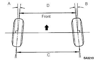
- Standard toe-in (unloaded vehicle):
Front A + B Rear C - D A + B: 0°05' +-10' (0.09° +-0.16°) C - D: 1.0 +-2.0 mm (0.04 +-0.08 in.)
If the toe-in is not as specified, adjust it at the rack ends.
INSPECT WHEEL ANGLE (FRONT WHEEL ALIGNMENT)
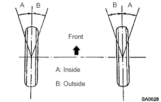
Turn the steering wheel to the left and right full lock positions, and measure the turning angle.
- Standard wheel angle (unloaded vehicle):
Inside Wheel Angle Outside Wheel Angle (Reference) 39°23' (37°23' to 41°23')
(39.4°(37.4° to 41.4°))32°29'
(32.5°)
If the angles are not as specified, check and adjust the right and left rack end lengths.
INSPECT CAMBER, CASTER AND STEERING AXIS INCLINATION (FRONT WHEEL ALIGNMENT)
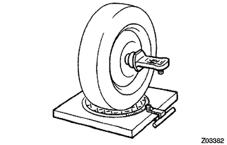
Install the camber-caster-kingpin gauge or place the front wheels on the center of the wheel alignment tester.
Inspect the camber, caster and steering axis inclination.
- Standard camber inclination (unloaded vehicle):
-0°10' +-45' (-0.16° +-0.75°)
- Standard caster inclination (unloaded vehicle):
5°45' +-45' (5.75° +-0.75°)
- Standard steering axis inclination (unloaded vehicle):
11° 22' +-45' (11.36° +-0.75°)
INSPECT TOE-IN (REAR WHEEL ALIGNMENT)
- Standard toe-in:
A + B C - D 0°17' +-22' (0.28° +-0.37°) 3.3 +-4.0 mm (0.13 +-0.16 in.)
If the toe-in is not within the specified range, inspect the suspension parts and replace them if necessary.
INSPECT CAMBER (REAR WHEEL ALIGNMENT)
Install the camber-caster-kingpin gauge or set the vehicle on the wheel alignment tester.
Inspect the camber.
- Standard camber:
Item Specified Condition Camber
Right-left error-1°24' +-30' (-1.40° +-0.5°)
30' (0.5°) or less
- HINT:
-
The camber is not adjustable. If the measurement is not within the specified range, inspect the suspension parts for damage and/or wear, and replace them if necessary.