Home › Suspension › FRONT SUSPENSION › FRONT SUSPENSION SYSTEM
NM24M0E _53 Suspension _061439 FRONT SUSPENSION _0299856 FRONT SUSPENSION SYSTEM UN GENERAL/CONTROL/DETAILS F

FRONT SUSPENSION  FRONT SUSPENSION SYSTEM  GENERAL/CONTROL/DETAILS  DETAILS  


CONSTRUCTION


a.

Lower Arm

i.

Closed cross section type lower arms that are lightweight and highly rigid are used.


ii.

The installation point of the lower arm bushing and the bushing characteristics have been optimized to realize excellent ride comfort and steering characteristics.


iii.

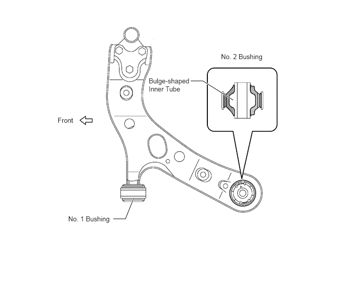
A type of bushing without an outer tube is used for the No. 1 bushing. An outer tube adhesion type is used for the No. 2 bushing, in which the bushing characteristics have been optimized through the use of a bulge-shaped inner tube.
X135892E01
2.333,4.51 2.583,4.51 2.583,4.51 2.75,4.094 true 3.927,1.667 4.177,1.667 4.177,1.667 4.802,2.063 true 4.552,1.083 5.708,1.385 1.156,0.302 10 false No. 2 Bushing 3.063,1.583 3.948,2.396 0.885,0.813 10 false Bulge-shaped Inner Tube 1.188,2.396 2.344,2.698 1.156,0.302 10 false Front 1.406,4.427 2.563,4.729 1.156,0.302 10 false No. 1 Bushing


b.

Suspension Upper Support

i.

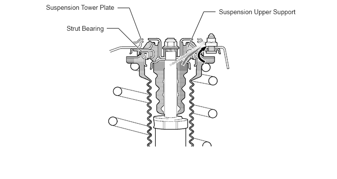
The characteristics of the suspension upper support, which has a separate type of input construction, have been changed. This construction transmits only the inputs from the shock absorber and the bound stopper via the suspension upper support to the body. Thus, it realizes superior quietness and ride comfort performance.


ii.

A suspension tower plate is used on top of the suspension tower. Accordingly, the localized distortion of the suspension tower has been reduced, resulting in excellent stability and controllability.

New Models:

·

Transmits the inputs from the shock absorber and bound stopper via the suspension upper support to the body.

·

Transmits the input from the coil spring via the strut bearing to the body.
X135894E01
4,1 4.333,0.25 4.333,0.25 4.583,0.25 true 2.5,0.167 2.75,0.167 2.75,0.167 3,0.833 true 2.271,0.604 2.521,0.604 2.521,0.604 3.021,1.104 true 4.656,0.167 6.583,0.427 1.927,0.26 10 false Suspension Upper Support 0.979,0.073 2.906,0.333 1.927,0.26 10 false Suspension Tower Plate 1.417,0.521 2.385,0.75 0.969,0.229 10 false Strut Bearing


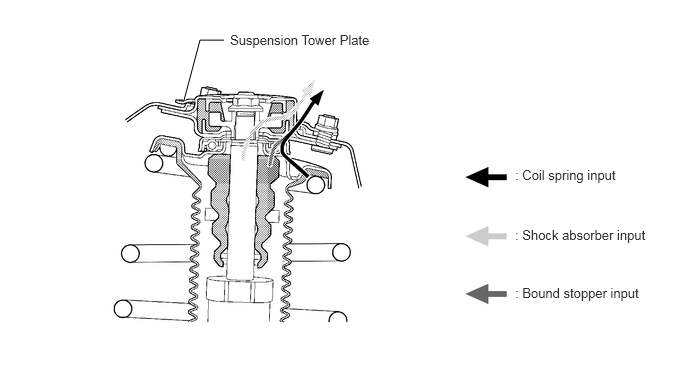
Previous Models:

·

Transmits the inputs from the shock absorber via the suspension upper support to the body.

·

Transmits the input from the coil spring and bound stopper via the strut bearing to the body.
X136187E01
2.333,0.417 2.083,0.417 2.083,0.417 1.917,1.042 true 2.396,0.333 4.396,0.875 2,0.542 10 false Suspension Tower Plate 5.365,1.74 6.521,2.094 1.156,0.354 10 false : Coil spring input 5.365,2.365 6.938,2.875 1.573,0.51 10 false : Shock absorber input 5.365,2.969 6.927,3.458 1.563,0.49 10 false : Bound stopper input


c.

Coil Spring

i.

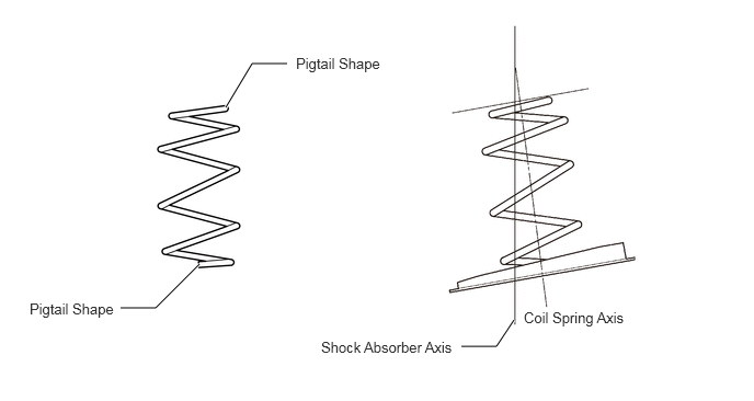
Both ends of the coil spring are pigtail-shaped, and made compact and lightweight.


ii.

The optimized shape of the spring and its installation position have reduced the lateral force that is applied to the shock absorber. Together with the smooth movement realized through reduced friction, excellent ride comfort and steering feel have been realized.
X136188E01
1.146,2.927 1.479,2.927 1.479,2.927 1.896,2.51 true 2.146,1.021 2.396,0.604 2.396,0.604 2.729,0.604 true 4.385,3.292 4.719,3.292 4.719,3.292 4.885,3.042 true 2.813,0.521 3.896,0.833 1.083,0.313 10 false Pigtail Shape 0.281,2.854 1.365,3.167 1.083,0.313 10 false Pigtail Shape 3.052,3.219 4.75,3.563 1.698,0.344 10 false Shock Absorber Axis 4.979,2.938 6.281,3.25 1.302,0.313 10 false Coil Spring Axis


d.

Shock Absorber

i.

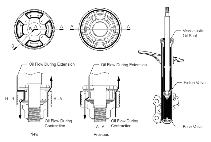
The piston valve uses a new type of valve construction. It realizes an excellent ride comfort by improving the damping response. The previous backing valve performed the function of a check valve through its ring-shaped seat construction. In contrast, the new valve construction enables the layering of the backing valves through the use of four independent seats. The layering of the backing valves enables both the piston valve and the base valve to bear the damping force during contraction. Thus, this shock absorber can generate the proper damping force even when the pressure difference is small.


ii.

A viscoelastic oil seal is used. This measures enable the shock absorber to generate damping force starting at an ultra-low speed range, and realize an excellent road holding feel and steering feel.
X136189E01
5.781,1.354 5.969,1.042 5.969,1.042 6.135,1.042 true 5.76,3.135 6.01,2.802 6.01,2.802 6.177,2.802 true 5.792,4.063 5.958,4.313 5.958,4.313 6.125,4.313 true 0.583,2.594 0.75,2.177 0.75,2.177 0.917,2.177 true 3.021,2.615 3.188,2.198 3.188,2.198 3.354,2.198 true 2.042,0.813 2.198,1.01 0.156,0.198 10 false A 2.396,0.813 2.552,1.01 0.156,0.198 10 false A 4.313,0.813 4.469,1.01 0.156,0.198 10 false A 1.167,0.813 1.323,1.01 0.156,0.198 10 false A 0.99,0.896 1.146,1.094 0.156,0.198 10 false B 0.385,1.479 0.542,1.677 0.156,0.198 10 false B 6.208,0.958 7.01,1.49 0.802,0.531 10 false Viscoelastic Oil Seal 6.24,2.719 7.104,3.052 0.865,0.333 10 false Piston Valve 6.208,4.219 7,4.542 0.792,0.323 10 false Base Valve 0.177,3.26 0.729,3.531 0.552,0.271 10 false B - B 1.823,3.271 2.281,3.479 0.458,0.208 10 false A - A 3.26,4.219 3.719,4.5 0.458,0.281 10 false A - A 0.979,2.094 2.708,2.365 1.729,0.271 10 false Oil Flow During Extension 1.521,4.021 2.51,4.479 0.99,0.458 10 false Oil Flow During Contraction 3.427,2.115 5.24,2.438 1.813,0.323 10 false Oil Flow During Extension 3.771,4.021 4.75,4.563 0.979,0.542 10 false Oil Flow During Contraction 1.031,4.469 1.49,4.719 0.458,0.25 10 false New 3.177,4.479 3.833,4.729 0.656,0.25 10 false Previous


e.

Stabilizer Bar

i.

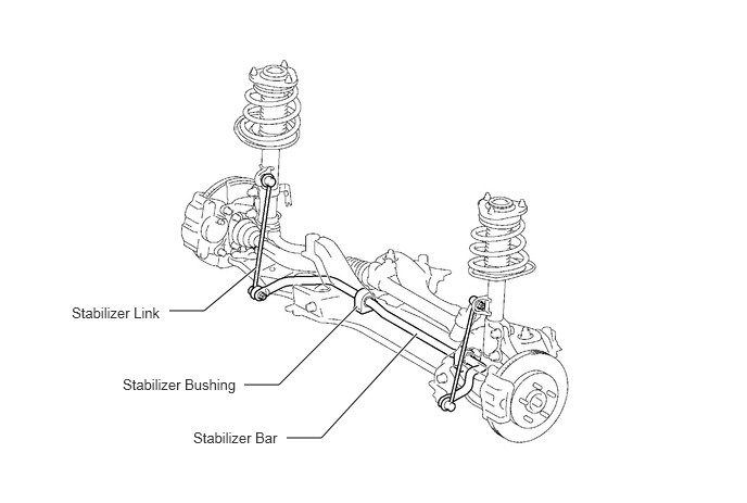
The stabilizer bar is made of a hollow bar, reducing the weight. A ball joint is used between the stabilizer link and the stabilizer bar, and between the stabilizer link and the shock absorber. This helps reduce suspension friction and increase link rigidity. As a result, the ball joints perform effectively even for slight rolling and maintain stable roll feeling.


ii.

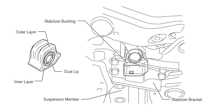
The surface of the stabilizer bushing that is installed to the suspension member has a saddle shape. This construction, which is embedded into the cross section of the suspension member, ensures excellent support rigidity.


iii.

The stabilizer bushing has a dual construction using the following materials: an outer layer made of highly rigid ordinary rubber, and an inner layer made of lowly rigid self-lubricating rubber. Thus, it realizes a high roll rigidity and ease of installation.


iv.

The stabilizer bushing has been provided with a dust lip to prevent sand from entering.
X135899E01
1.625,2.979 1.958,2.979 1.958,2.979 2.458,2.563 true 2.344,3.688 2.677,3.688 2.677,3.688 3.427,2.938 true 2.75,4.198 3.083,4.198 3.083,4.198 4,3.198 true 0.688,2.917 2.146,3.24 1.458,0.323 10 false Stabilizer Link 1.177,3.604 2.635,3.927 1.458,0.323 10 false Stabilizer Bushing 1.854,4.115 3.313,4.438 1.458,0.323 10 false Stabilizer Bar

X136190E01
1.333,1.104 1.583,1.104 1.583,1.104 1.729,1.656 true 1.219,2.833 1.469,2.833 1.469,2.833 1.552,2.333 true 2.167,2.5 1.917,2.5 1.917,2.5 1.75,2.083 true 2.719,0.729 2.969,0.729 2.969,0.729 4.469,2.229 true 2.833,3.469 3.083,3.469 3.083,3.469 4.26,3.156 true 5.354,2.885 5.688,3.479 5.688,3.479 5.938,3.479 true 0.552,1.031 1.646,1.271 1.094,0.24 10 false Outer Layer 2.25,2.417 3.344,2.656 1.094,0.24 10 false Dust Lip 0.49,2.771 1.583,3.01 1.094,0.24 10 false Inner Layer 1.552,0.656 3.146,1 1.594,0.344 10 false Stabilizer Bushing 1.521,3.385 3.552,3.583 2.031,0.198 10 false Suspension Member 6,3.396 7.146,3.625 1.146,0.229 10 true Stabilizer Bracket