PARK ASSIST / MONITORING TOYOTA PARKING ASSIST-SENSOR SYSTEM GENERAL/CONTROL/DETAILS DETAILS
FUNCTION OF MAIN COMPONENTS
| Component | Function |
|---|---|
| Ultrasonic Sensor | Detects and calculates the distance between the vehicle and the obstacle. |
| Clearance Sonar Switch | Turns the front and rear clearance sonar system ON. |
| Clearance Sonar Buzzer | Emits an intermittent sound to inform the driver that the clearance sonar ECU has detected an obstacle within the prescribed range. |
| Clearance Sonar ECU | Judges the approximate distance between the vehicle and obstacle based on the signals from the ultrasonic sensors and sends the indicator signal to the indicator and the buzzer signal to the buzzer. Additionally, the clearance sonar ECU has a buzzer sound volume adjusting knob. |
| Clearance Sonar Indicator | Displays the location of the obstacle and the approximate distance between the vehicle and the obstacle. |
SYSTEM CONTROL
Detection Activation
This system activates when the power source mode is IG-ON, the clearance sonar switch is turned ON, and the conditions shown below have been met.
| Sensor | Shift Position | ||
|---|---|---|---|
| P | R | Other than P or R | |
|
○: Detection |
|||
| Front Corner Sensor | - | ○ | ○ |
| Rear Corner Sensor | - | ○ | - |
| Back Sensor | - | ○ | - |
Detection Range
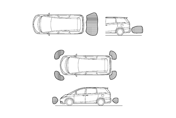
Initial Check (Self-diagnosis)
After the Toyota parking assist system has been activated, it illuminates the indicator light and sounds the buzzer for about 1 second, while checking for any malfunction in the ultrasonic sensors. If the system cannot activate its detection function due to a malfunction in an ultrasonic sensor, it alerts the driver of the malfunction by the indicator light for the malfunctioning area and the buzzer in synchronization with the flashing light. For details, refer to the Repair Manual.
CONSTRUCTION
Ultrasonic Sensor
The ultrasonic sensors are provided with a distance calculation function in order to digitalize the signals between the clearance sonar ECU and the ultrasonic sensor. As a result, the number of wiring harnesses has been reduced.
The following numbers of ultrasonic sensors are provided: 2 along the front corners, 2 along the rear corners, and 2 on the back centers. Each ultrasonic sensor consists of a sensor portion that transmits and receives ultrasonic waves and a pre-amplifier that amplifies them. The distance calculation circuit calculates the distance between the vehicle and the obstacle based on the received ultrasonic waves. The ultrasonic sensors transmit the calculated distance signals to the clearance sonar ECU.
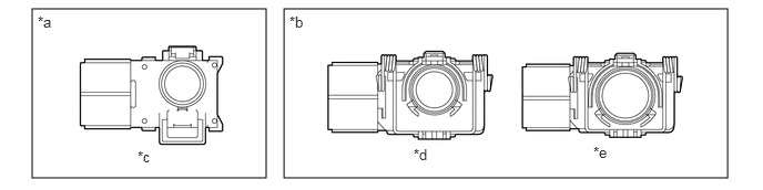
| *a | New | *b | Previous |
| *c | For Corner and Center | *d | For Corner |
| *e | For Center | - | - |
Clearance Sonar Buzzer
The buzzer is installed in the heater control panel.
Clearance Sonar Indicator and Clearance Sonar Switch
A switch that turns the power of this system ON/OFF, an obstacle detection display, and a buzzer are provided in the heater control panel.
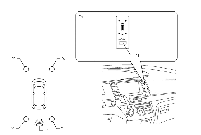
| *1 | Clearance Sonar Switch | - | - |
| *a | Illuminates all the power, back sonar, and clearance sonar indicator lights. | *b | Front Left Side |
| *c | Front Right Side | *d | Rear Left Side |
| *e | Back Sonar | *f | Rear Right Side |
Clearance Sonar ECU
The clearance sonar ECU effects overall control of the system, including the switching of the transmission, reception of the ultrasonic sensor signals, processing the received wave signals, determining the presence of obstacles, actuating the warning indicators and buzzer, and detecting an open circuit in the sensors.
The sound volume of the clearance sonar buzzer can be adjusted at the clearance sonar ECU.
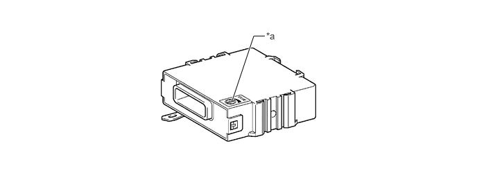
| *a | Buzzer Sound Adjusting Knob | - | - |
OPERATION
Ultrasonic Sensor
When the vehicle speed is 10 km/h (6.25 mph) or more.
The shift lever position for all sensors:
| Sensor | Shift Position | |
|---|---|---|
| R | Except R | |
| Front Corner Sensor | Detection | Detection |
| Rear Corner Sensor | Detection | Prohibition |
| Back Sensor | Detection | Prohibition |
When sensors are abnormal in open and freezing detection, and obstacle detection.
Clearance Sonar Buzzer
The ON/OFF times of the clearance sonar buzzer vary in accordance with the distance to the obstacle as shown in the following table:
| Item | Buzzer | Sensor Detection Level | Distance to Obstacle [cm (in.)] | ON Time (ms) | OFF Time (ms) |
|---|---|---|---|---|---|
| Front Corner Sensor | 2.4 kHz | 2nd | Approx. 50 (19.7) to 37.5 (14.8) | 150 +/- 15 | 150 +/- 15 |
| 3rd | Approx. 37.5 (14.8) to 25 (9.8) | 75 +/- 7.5 | 75 +/- 7.5 | ||
| 4th | Approx. 25 (9.8) or less | Continuous | 0 | ||
| Rear Corner Sensor | 2nd | Approx. 50 (19.7) to 37.5 (14.8) | 150 +/- 15 | 150 +/- 15 | |
| 3rd | Approx. 37.5 (14.8) to 25 (9.8) | 75 +/- 7.5 | 75 +/- 7.5 | ||
| 4th | Approx. 25 (9.8) or less | Continuous | 0 | ||
| Back | 1st | Approx. 150 (59.1) to 60 (23.6) | 150 +/- 15 | 650 +/- 65 | |
| 2nd | Approx. 60 (23.6) to 45 (17.7) | 150 +/- 15 | 150 +/- 15 | ||
| 3rd | Approx. 45 (17.7) to 35 (13.8) | 75 +/- 7.5 | 75 +/- 7.5 | ||
| 4th | Approx. 35 (13.8) or less | Continuous | 0 |
Attentive Information Conditions and Buzzer Beeping Pattern
The ultrasonic sensors are grouped into front sensors: front corner sensors, and rear: rear corner sensors and back sensors.
The following table indicates the changes in buzzer beeping patterns depending on obstacle detection.
It also shows the pattern changes in regard to detection by both front and rear groups.
| Back Sensor Detection Level | Corner Sensor Detection Level | |||
|---|---|---|---|---|
| 4th | 3rd | 2nd | Non Detection | |
|
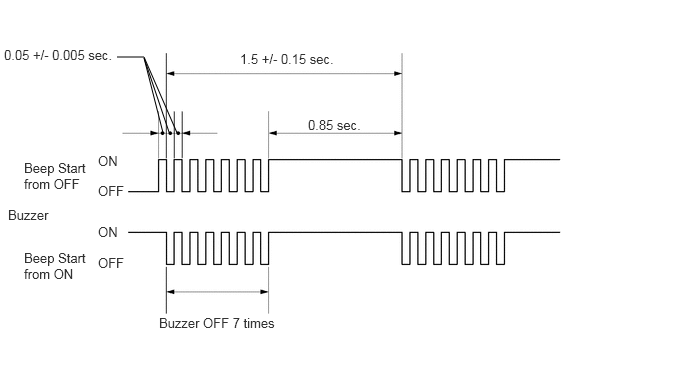
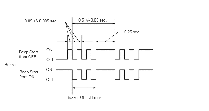
*1: A 1.5-second cycle, which comprises 0.65 seconds of an intermittent beep (ON/OFF) period and 0.85 seconds of a continuous beep period, is repeated. *2: A 0.5-second cycle, which comprises 0.25 seconds of an intermittent beep (ON/OFF) period and 0.25 seconds of a continuous beep period, is repeated. |
||||
| 1st | Pattern B*2 | Pattern A*1 | Pattern A*1 | Continuous Beep |
| 2nd | Pattern A*1 | 0.15 sec. | 0.15 sec. | 0.15 sec. |
| 3rd | Pattern A*1 | 0.15 sec. | 0.3 sec. | 0.3 sec. |
| 4th | Pattern A*1 | 0.15 sec. | 0.3 sec. | 0.8 sec. |
| Non Detection | Continuous Beep | 0.15 sec. | 0.3 sec. | No Beep |