PARK ASSIST / MONITORING PARKING ASSIST MONITOR SYSTEM GENERAL/CONTROL/DETAILS DETAILS
FUNCTION OF MAIN COMPONENTS
| Item | Function |
|---|---|
|
*1: Models with Power Back Door System *2: Models without Power Back Door System |
|
| Television Camera | ·
Transmits an image of the area behind the vehicle to the navigation receiver assembly. ·
A color video camera that uses a Charge Coupled Device (CCD) and a wide-angle lens. |
| Navigation Receiver Assembly | ·
Receives video signals, which contain an image of the area behind the vehicle taken with the rear television camera assembly. ·
Performs overall control of the system by receiving signals from the sensors. ·
Allows operation via the touch panel of the display when the park assist monitor screen or diagnosis screen is displayed. ·
Creates images and displays adjustment screens performed on the diagnosis screen. ·
Stops displaying the guide line and buttons displays "Check surrounding for safety" when an open signal is received for the back door. |
| Park/Neutral Position Switch Assembly | Sends the reverse signal to the navigation receiver assembly. |
| Combination Meter Assembly | Sends a vehicle speed signal to the navigation receiver assembly. |
| Steering Sensor | Detects the angle of the steering wheel and sends the resulting signals to the navigation receiver assembly via CAN communication. |
| Main Body ECU (Instrument Panel Junction Block Assembly) | Sends a back door open/close signals to the navigation receiver assembly via CAN communication. |
| Power Back Door ECU (Back Door Motor Unit)*1 | Sends a back door open/close signals to the main body ECU (instrument panel junction block assembly) via CAN communication. |
| Back Door Lock Assembly | Detects the back door open/close status and sends that signal to the main body ECU (instrument panel junction block assembly)*2 or power back door ECU (back door motor unit)*1. |
SYSTEM CONTROL
The television camera ECU controls the system by using information from the following sources: steering angle sensor signal, vehicle posture from the navigation ECU, vehicle speed signal, and neutral start switch signal.
Area Displayed on Display Panel
On the radio and player with display, objects on the right of the vehicle appear on the right side of the display panel, and objects on the left of the vehicle appear on the left side of the display panel.
The television camera uses a wide-angle lens. The perceived distance from images that appear on the display panel differs from the actual distance.
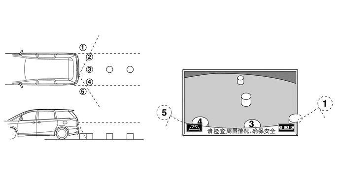
- HINT:
- ·
Area displayed on display panel may vary according to vehicle status or road conditions.
·The area covered by the television camera is limited. The television camera dose not show objects close to either corner of the bumper or under bumper.
Initialize Function during Part Replacement
The initialize function must invariably be performed whenever one of the conditions indicated in the table below occurs.
| Parts Name | Condition | Initialize Item |
|---|---|---|
| Television Camera | ·
Camera position shifted ·
Removal and reassembly ·
Replacement ·
Deformed when the mounted area is struck |
Camera position adjustment
·
Vertical position ·
Horizontal position ·
Roll angle, pan angle, tilt angle |
| Television Camera ECU | Replacement | ·
Neutral steering point in memory ·
Maximum side-to-side steering angle in memory ·
Camera position adjustment -
Vertical position -
Horizontal position -
Roll angle, pan angle, tilt angle |
| Steering Angle Sensor | ·
Replacement ·
Removal and reassembly |
·
Neutral steering point in memory ·
Maximum side-to-side steering angle in memory |
The initialize function described above is performed on the diagnosis menu screen.
The method for starting the diagnosis menu screen is the same as in the navigation system.
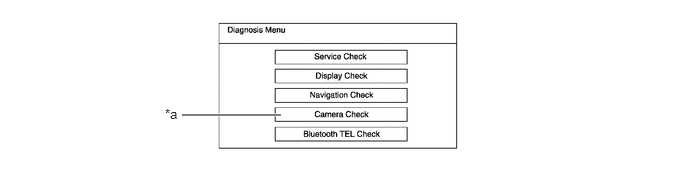
| *a | Select this menu. | - | - |
FUNCTION
Warning Message
A warning message appears at the bottom or the center of the screen under the conditions listed below, regardless of whether the system is in the manual or parallel parking assist mode.
| Warning Message | Outline |
|---|---|
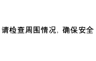
|
This message always appears during system operation. |
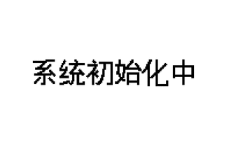
|
This message appears when the system is restarted if the television camera ECU detects that a battery terminal has been disconnected and subsequently reconnected. |
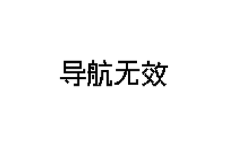
|
This message is displayed when the vehicle is moved backward further, even though a message, "Steering wheel turned too far, please return", is displayed in the center of the display and also the system judges it is impossible to perform the assist operation. |
| Warning Message | Outline |
|---|---|
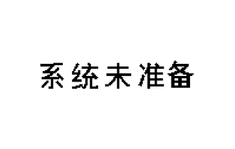
|
This message appears if the system is started without initializing after a part is replaced. |
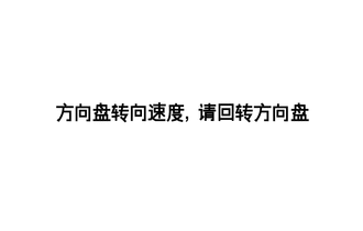
|
This message is displayed when the system cannot perform the assist operation under the following situations:
·
When the vehicle starts in the parallel parking assist mode, a side-to-side clearance between your vehicle and the other parked vehicles is not approximately 1 m (3.3 ft.) (too far or too close). ·
The steering wheel is turned too far. |
Fail-safe Function
The table below indicates the conditions of detecting malfunctions in the sensors and ECUs in this system.
| Malfunction Part | Detection Item | Function | |
|---|---|---|---|
| Manual Assist Mode | Parallel Parking Assist Mode | ||
| Steering Angle Sensor | ·
Transmission of sensor malfunction signal ·
Open circuit in sensor signal |
- | Switches to the manual assist mode automatically. |
| Transmission of signal of incompletion of neutral steering point correction | - | Displays "System initializing". | |
| Communication malfunction between the steering angle sensor and television camera ECU | - | Switches to the manual assist mode automatically. | |
| Television Camera | Transmission of television camera malfunction signal | Stops signal reception and displays a dark screen. | |
| Television Camera ECU | Malfunction of television camera ECU unit | Stops system operation. | |
| Navigation ECU | ·
No response from navigation ECU ·
Transmission of navigation ECU malfunction signal |
- | Switches to the manual assist mode automatically. |
Self-diagnosis Function
The parking assist monitor is equipped with a self-diagnosis system and can display the diagnosis menus shown on the right.
The diagnosis menu that pertains to this system contains the following three items:

| *a | Service Check | *b | Display Check |
| *c | Camera Check | - | - |
The method for starting the diagnosis menu screen is the same as in the navigation system.
CONSTRUCTION
Description of Display
General
This system displays the following two modes: the manual assist mode used for parking the vehicle in a garage or parking area, and the parallel parking assist mode, which assists the driver by providing the appropriate steering angle and timing during serial parking.
The driver can switch the system modes by pressing the touch switch, although the display is initially set to the parallel parking assist mode at the factory. The ECU stores in its memory the mode at the time the power source mode is selected to OFF. Therefore, the mode that is stored in the ECU appears when the power source mode is subsequently selected to IG-ON.
Manual Assist Mode
When the system operates in the manual assist mode, fixed guide lines appear with the rearview of the vehicle as illustrated below. These guide lines can be used to assist the driver while the vehicle is moving backward.
In this mode, the driver can press the changeover switch on the display to change the guide line pattern.
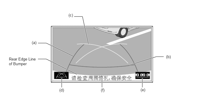
| Item | Description of Display | ||
|---|---|---|---|
| (a) | Vehicle Width Extension Line | A guide line for assisting the driver's assessment of the width of the vehicle. | |
| (b) | Distance Guide Line (Red) | A guide line that serves as a reference for the driver to assess the distance from the rear of the vehicle. {Approximately 50 cm (1.6 ft.) from rear end of bumper} | |
| (c) | Parking Guide Line | A guide line indicating the prospective outer path of the vehicle when the steering is turned fully to the right or left end. | |
| (d) | Changeover Switch | Three guide line patterns are available, and can be switched by pressing this switch. | |
| (e) | Touch Switch | Manual Assist Mode | The system switches from the manual assist mode to the parallel parking assist mode by pressing this switch. |
| Parallel Parking Assist Mode | |||
| (f) | Warning Message Display Area | Displays a warning message. | |
Parallel Parking Assist Mode
In this mode used for parallel parking, the ECU switches the display of the guide lines in accordance with the parking maneuvers of the vehicle. This provides the driver with an appropriate steering angle and timing during parallel parking.
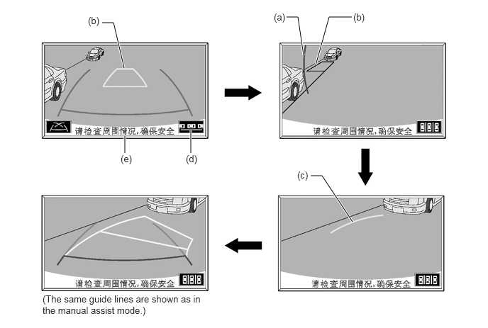
| Item | Description of Display | ||
|---|---|---|---|
| (a) | Green Vertical Line | A guide line that serves as a reference position for starting parallel parking. | |
| (b) | Distance Guide Line (Red) | A guide line that serves as a reference position for completing the intended parking. This guide line disappears once the vehicle starts moving backward. | |
| (c) | Parking Guide Line | A guide line indicating part of the prospective outer path of the vehicle when the steering is turned fully to the right or left end. This guide line appears only after the guide lines (a) and (b) disappear. | |
| (d) | Touch Switch | Manual Assist Mode | The system switches from the parallel parking assist mode to the manual assist mode when this switch is pressed. |
| Parallel Parking Assist Mode | |||
| (e) | Warning Message Display Area | Displays a warning message. | |
OPERATION
Some examples of operating the system in the manual assist mode and parallel parking assist mode are listed below.
Manual Assist Mode
To use the manual assist mode to park the vehicle in the parking space illustrated below, perform the following procedure:
Move the shift lever to reverse.
Verify that the manual assist mode is selected.
An image appears on the display panel as illustrated on the right.
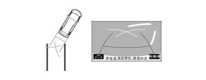
Back the vehicle and stop at the position in which the parking guide line comes in contact with the left side of the intended parking position.
Turn the steering wheel fully to the right and back the vehicle.
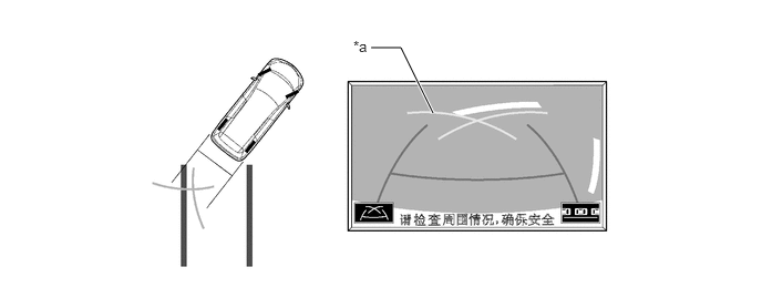
| *a | Parking Guide Line | - | - |
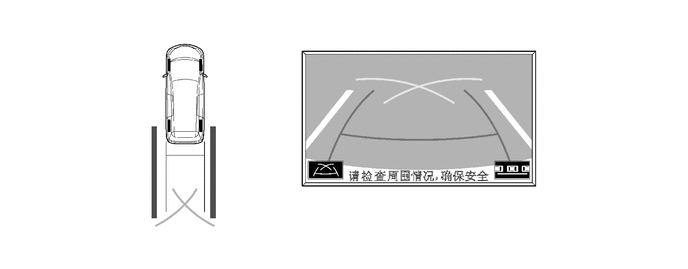
Continue backing the vehicle until the vehicle is parallel to the plotted lines.
Once the vehicle is parallel, aim the steering wheel straight ahead and back the vehicle to the target stop position.
Perpendicular Parking Mode
To use the perpendicular parking mode to park the vehicle in the parking space illustrated below, perform the following procedure:
Move the shift lever to reverse.
Verify that the perpendicular parking mode is selected.
An image appears on the display panel as illustrated on the right.
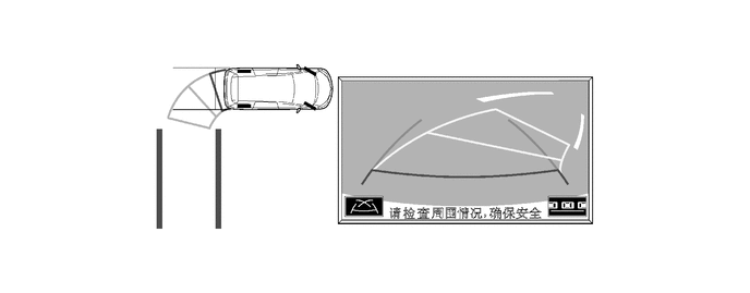
Back the vehicle and stop at the position in which the anticipated pathway line comes in contact with the left side of the intended parking position.
Turn the steering wheel fully to the right and back the vehicle.
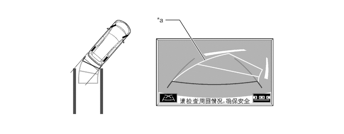
| *a | Anticipated Pathway Line | - | - |
Continue backing the vehicle until the vehicle is parallel to the plotted lines.
Once the vehicle is parallel, aim the steering wheel straight ahead.
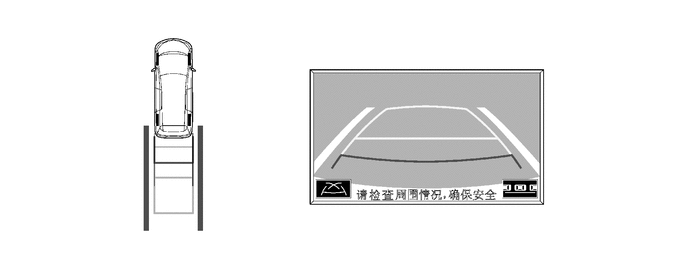
Continue backing the vehicle until the vehicle is in the target stop position. You can use the distance guide line (red, 50cm (1.64 ft) from the vehicle) as a reference. However, make sure to visually check directly.
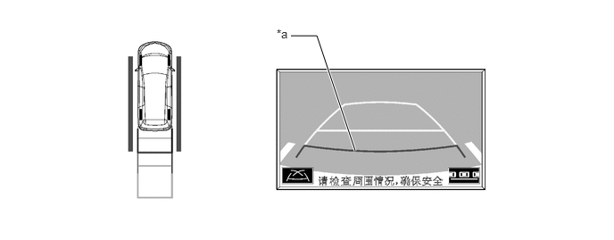
| *a | Distance Guide Line | - | - |
Parallel Parking Assist Mode
To use the parallel parking assist mode to park the vehicle in the parking space illustrated below, perform the following procedure:
Stop the vehicle parallel to the road or the curb, at a side-to-side clearance of approximately 1 m (3.3 ft.) from the parked vehicle, approximately one-half car length forward of the parked vehicle.
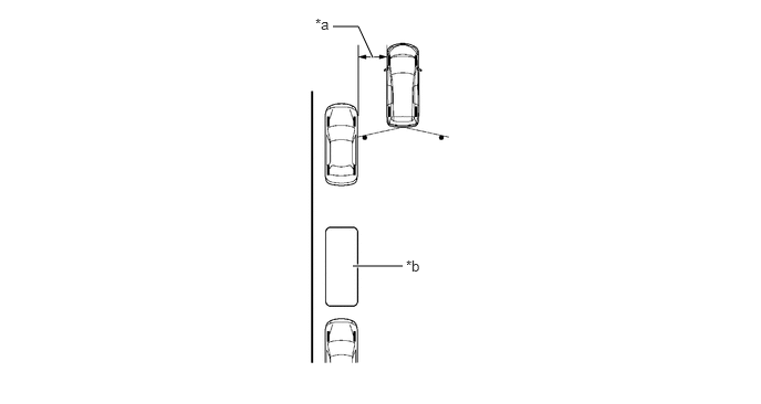
| *a | Approx. 1 m (3.3 ft.) | *b | Target Parking Position |
Aim the steering wheel straight ahead and move the shift lever to reverse.
Verify that the parallel parking assist mode is selected.
An image shows on the display panel as illustrated on the right.
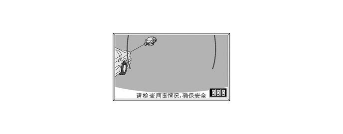
Drive the vehicle straight back and stop when the green vertical line of the target parking position is aligned with the rear end of the parked vehicle.
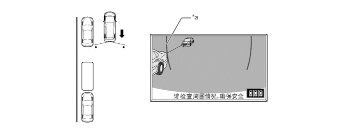
| *a | Green Vertical Line | - | - |
The green outline appears on the screen after 5 seconds elapse from the time the shift lever is moved to reverse, or if the steering wheel is turned with the vehicle at a standstill.
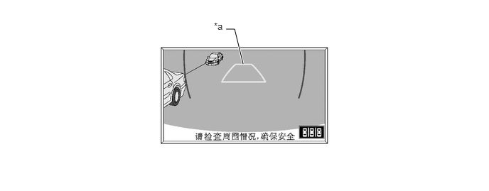
| *a | Green Outline | - | - |
Continue turning the steering wheel, and the green outline will move in the direction of the target parking position, while the outline changes into a shape as illustrated on the right. Keep turning the steering wheel until the green outline reaches the target parking position. At this time, the green vertical line opposite to the target parking position disappears when the steering wheel is turned more than 90 degrees.
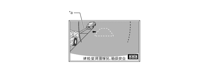
| *a | Green Outline | - | - |
However, if the steering wheel is turned too much, the message as shown in the right illustration is displayed and the green outline change to red to inform the driver that the assist operation is not capable. Also, when your vehicle is away from the shoulders too much, the same condition will occur even adjusting the green outline at the normal position.
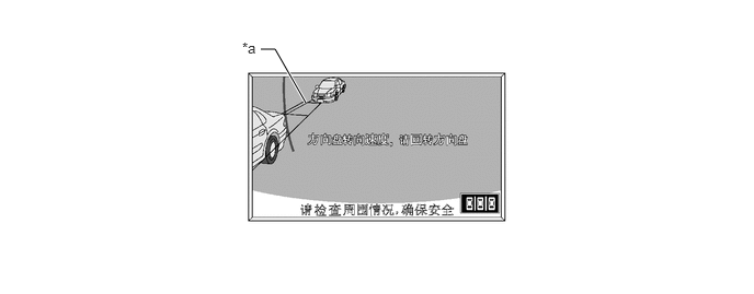
| *a | The green outline changes to red. | - | - |
Keep the steering wheel in the same position and start backing up. Then, the green vertical line and green outline disappear, and a parking guide line (maximum steering angle line) appears in the direction of the target parking position.
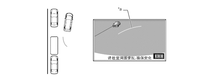
| *a | Parking Guide Line | - | - |
Keep the steering wheel in the same position and back up. Stop when the parking guide line reaches the left end of the target parking position.
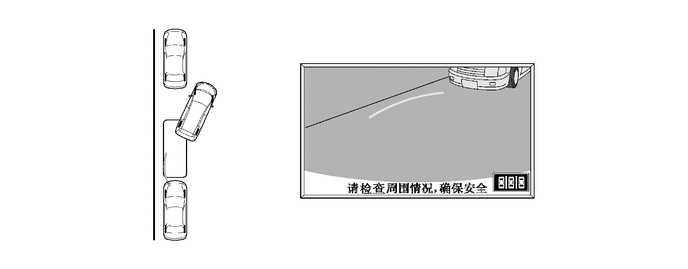
With the vehicle at a standstill, fully turn the steering wheel in the opposite direction. Then, as illustrated on the right, the same guide line appears as in the manual assist mode.
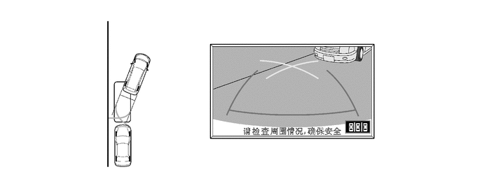
Using the distance guide line, slowly back the vehicle until the vehicle is parallel to the road or curb, while paying attention to the vehicles in front and in back. The parking maneuver is completed once the vehicle is parallel.
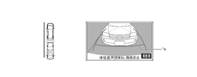
| *a | Distance Guide Line | - | - |
- HINT:
-
If a "System initializing" appears, the assist function will not operate properly. This is because the present neutral steering point that is detected by the steering angle sensor dose not match the neutral steering point that is stored in the memory of the television camera ECU. Therefore, if the television camera ECU detects that a battery terminal has been disconnected and the system is operated again by subsequently reconnecting the battery terminal, a "System initializing" warning message appears at the bottom of the screen. When this occurs, take one of the following corrective actions:
- ·
With the power source mode IG-ON and the vehicle at a standstill, fully turn the steering wheel to the right, then fully turn it to the left (this procedure can be started either with a right or left turn).
·Drive the vehicle for approximately 5 minutes on the road with a minimal number of curves.