DOOR / HATCH POWER SLIDE DOOR SYSTEM GENERAL/CONTROL/DETAILS DETAILS
FUNCTION OF MAIN COMPONENTS
The functions of the main components are described below:
| Components | Function |
|---|---|
|
*1: Models without Smart Entry & Start System *2: Models with Smart Entry & Start System |
|
| Power Slide Door Drive Unit | The power slide door ECU, which is built into the power slide door motor, receives the signals from the main body ECU and the switches. Then, this unit automatically opens or closes the slide door by actuating the power slide door motor in accordance with the operation request signal received from the power slide door ECU. |
| Power Slide Door Lock Assembly (with Full Lock Motor) | Actuates the built-in full lock motor forward or backward to fully close the slide door if it is ajar, and to open it to the ajar position if it is fully closed. |
| Power Slide Door Lock Release Motor Assembly | Releases the latch of the power slide door remote control assembly when the power slide door switch or transmitter is operated. |
| Power Slide Door Lock Remote Control Assembly | Actuates the built-in full lock motor forward or backward to lock or unlock the slide door. |
| Power Slide Door Front Lock Assembly | Releases or locks the latch in front of the slide door. |
| Half Open Stopper (Only for LH) | Restricts the operation of the stopper or controls the operation of the power slide operation of the slide door while the fuel lid or power window is open. |
| Full Open Stopper | The interlock type full open stopper prevents the slide door from closing accidentally by its own weight when the vehicle is parked on a slope. |
| Touch Sensor | Detects the presence of a jammed object while the slide door is moving in the closing direction. |
| Power Supply Equipment Unit | Provides continuous power to the various units in the power slide door system. |
| PWR DOOR OFF Switch | Turns the power slide door system ON/OFF. |
| Power Slide Door Switch | Opens and closes the slide door. |
| Inside/Outside Door Handle | Transmits slide door open and close signals to the power slide door ECU. |
| Transmitter | Transmits slide door open and close signals to the wireless door lock receiver*1 or tuner*2. |
| Wireless Door Lock Receiver*1 or Tuner*2 | Receives slide door open and close signals from the transmitter. |
| Main Body ECU | Receives slide door open and close signals from the wireless door lock receiver*1 or tuner*2 and outputs them to the power slide door ECU. |
SYSTEM CONTROL
General
The following slide door operations are available: assist operation (to slightly open and close the slide door manually), inside/outside door handle operation, power slide door switch operation, and transmitter operation.
The slide door will stop in the middle if the fuel lid or the power window is open while the slide door is being opened.
Operating Conditions
| Power Source Mode | Operating Condition
(The slide door operates only when all the conditions below have been met.) |
|---|---|
|
*1: An open slide door can be closed even if it is locked. *2: This is applicable only to the left slide door. The right slide door can be operated even when the fuel lid is open. |
|
| IG-ON | PWR DOOR OFF switch is ON |
| Slide door is unlocked *1 | |
| Fuel lid is closed *2 | |
| Battery voltage is 10.5V or more | |
| The shift lever is in the P position | |
| The vehicle speed is 3km/h (1.9 mph) or less | |
| OFF | PWR DOOR OFF switch is ON |
| Slide door is unlocked *1 | |
| Fuel lid is closed *2 | |
| Battery voltage is 10.5V or more | |
FUNCTION
The power slide door system has the following functions:
| Function | Outline |
|---|---|
| Auto Open-and-close | Enables the slide door to open or close automatically through the operation of the following switches:
·
Power slide door switch ON the overhead console. ·
Transmitter. ·
Inside or outside door handle. |
| Touch Sensor Protection | If the touch sensor that is provided at the front end of the slide door becomes compressed while the slide door is moving in the closing direction, the resistance of the sensor changes. This change in resistance is output to the power slide door ECU to detect the presence of a jammed object. In addition, the power slide door ECU detects the presence of a jammed object when it detects a change in the moving speed of a slide door (by monitoring the motor speed). |
| Continuous Power Supply System | The adoption of the continuous power supply system for the slide door makes the junction power supply relay unnecessary, resulting in a simpler system. |
| Emergency Stop Function | If operation of the power slide door switch, power slide button or door handle is detected 3 times in a row while the power slide door is operating, the power slide door operation is stopped. |
| Diagnosis | When the power slide door ECU detects a malfunction in the power slide door system, it diagnoses the failed section. Intelligent tester II performs DTC check. For details, see Repair Manual. |
| Fail-safe | If any of the malfunctions listed below is detected during a power slide door operation, the power slide door ECU stops the power slide door motor. Then, it disengages the magnetic clutch and stops the operation of the system.
·
When the ECU does not detect an OFF signal from the half latch switch within 3 seconds after the power slide door motor has started its open operation. ·
When the ECU does not detect an OFF signal from the full latch switch within 3 seconds after the power slide door motor has started its close operation. ·
When the power slide door motor actuation period exceeds 30 seconds. |
Auto Open Function
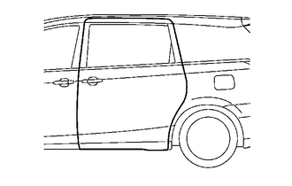
When the power slide door switch, transmitter, or inside/outside door handle is operated while a slide door is fully closed, the power slide door ECU receives an open operation signal and emits an operation warning sound through the power slide door warning buzzer. At the same time, the power slide door ECU controls the power slide door lock release motor and the power slide door motor to fully open the slide door.
| Operation | Power Slide Door Warning Buzzer |
|---|---|
| Power slide door switch is operated for 0.5 seconds or more | Continues to sound while the power slide door switch is being operated. |
| Transmitter is operated for 1.0 second or more | Continues to sound while the transmitter is being operated. |
| Inside/outside door handle is operated | Sounds for approximately 0.1 seconds. |
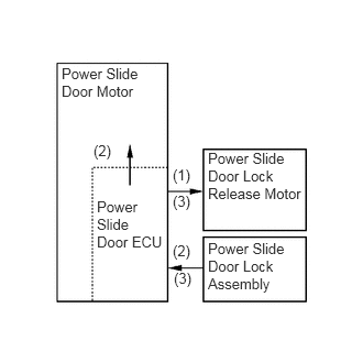
The power slide door ECU actuates the power slide door lock release motor to disengage the slide door lock.(1)
Actuates the power slide door motor upon receiving an ON signal from the full latch switch in the power slide door lock assembly.(2)
Stops the power slide door lock release motor upon receiving an ON signal from the half latch switch in the power slide door lock assembly.(3)
| Slide Door Condition | Control Signal |
|---|---|
|
0.583,0.615 1.354,0.979
0.771,0.365
10
false
Power Slide Door Motor
0.885,1.344 1.135,1.552
0.25,0.208
10
false
(2)
1.635,1.573 1.885,1.792
0.25,0.219
10
false
(1)
1.635,1.823 1.854,2.042
0.219,0.219
10
false
(3)
1.635,2.292 1.885,2.51
0.25,0.219
10
false
(2)
1.646,2.552 1.875,2.74
0.229,0.188
10
false
(3)
0.917,1.875 1.531,2.604
0.615,0.729
10
false
Power Slide Door ECU
1.969,1.417 2.844,2.104
0.875,0.688
10
false
Power Slide Door Lock Release Motor
1.969,2.271 2.854,2.823
0.885,0.552
10
false
Power Slide Door Lock Assembly
|
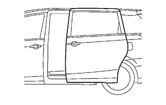
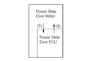
The power slide door ECU actuates the power slide door motor until the slide door is fully open.(4)
During this operation, the power slide door ECU detects the position of the slide door by way of the pulse signals provided by the Hall ICs in the power slide door motor.(5)
| Slide Door Condition | Control Signal |
|---|---|
|
1.292,0.323 2.073,0.75
0.781,0.427
10
false
Power Slide Door Motor
1.333,0.833 1.583,1.031
0.25,0.198
10
false
(5)
1.99,0.844 2.219,1.042
0.229,0.198
10
false
(4)
1.417,1.25 2.188,1.646
0.771,0.396
10
false
Power Slide Door ECU
|
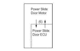
Upon detecting the full open position by way of the pulse signals from the Hall ICs in the power slide door motor, the power slide door ECU stops the power slide door motor, and turns OFF the magnetic clutch in the motor.(6)
| Slide Door Condition | Control Signal |
|---|---|
|
1.323,0.302 2.104,0.688
0.781,0.385
10
false
Power Slide Door Motor
1.656,0.844 1.906,1.031
0.25,0.188
10
false
(6)
1.396,1.229 2.177,1.656
0.781,0.427
10
false
Power Slide Door ECU
|
Auto Close Function
When the power slide door switch, transmitter, or inside/outside door handle is operated while a slide door is fully open, the power slide door ECU receives a close operation signal and emits an operation warning sound through the power slide door warning buzzer, and starts a close operation. At the same time, the power slide door ECU controls the power slide door lock release motor and the power slide door motor to fully close the slide door. The buzzer sounds intermittently while the slide door is operating.
| Operation | Power Slide Door Warning Buzzer |
|---|---|
| Power slide door switch door is operated 0.5 second or more | Continues to sound while the power slide door switch is being operated. |
| Transmitter is operated for 1.0 second or more | Continues to sound while the transmitter is being operated. |
| Inside/outside door handle is operated | Sounds approximately for 0.3 second. |
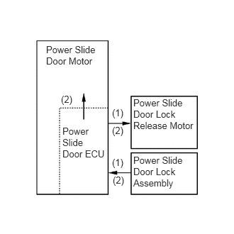
The power slide door ECU turns ON the magnetic clutch in the power slide door motor to actuate the power slide door lock release motor.(1)
Starts the actuation of the power slide door motor while the power slide door lock release motor is operating and verifies that the full open stopper is disengaged.(2)
| Slide Door Condition | Control Signal |
|---|---|
|
|
0.677,0.646 1.479,1.052
0.802,0.406
10
false
Power Slide Door Motor
0.896,1.375 1.146,1.583
0.25,0.208
10
false
(2)
0.917,1.844 1.531,2.375
0.615,0.531
10
false
Power Slide Door ECU
1.646,1.573 1.885,1.781
0.24,0.208
10
false
(1)
1.646,1.833 1.896,2.031
0.25,0.198
10
false
(2)
1.656,2.563 1.875,2.76
0.219,0.198
10
false
(2)
1.646,2.302 1.885,2.51
0.24,0.208
10
false
(1)
1.958,1.427 2.854,2.094
0.896,0.667
10
false
Power Slide Door Lock Release Motor
1.958,2.271 2.844,2.802
0.885,0.531
10
false
Power Slide Door Lock Assembly
|
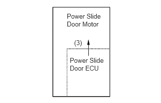
The power slide door ECU actuates the power slide door motor until it receives an OFF signal from the half latch switch in the power slide door lock assembly.(3)
| Slide Door Condition | Control Signal |
|---|---|
|
|
1.427,0.26 2.208,0.656
0.781,0.396
10
false
Power Slide Door Motor
1.583,0.823 1.833,1.021
0.25,0.198
10
false
(3)
1.49,1.198 2.271,1.656
0.781,0.458
10
false
Power Slide Door ECU
|
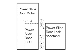
The power slide door ECU actuates the full lock motor simultaneously with the detection of an OFF signal from the half latch switch in the power slide door lock assembly.(4)
Stops the power slide door motor upon detecting that the pawl switch in the power slide door lock assembly has been turned from ON to OFF.(5)
Stops the full lock motor upon detecting an OFF signal from the full latch switch and the pawl switch in the power slide door lock assembly, thus ending the full close operation of the slide door.(6)
| Slide Door Condition | Control Signal |
|---|---|
|
|
0.771,0.292 1.542,0.677
0.771,0.385
10
false
Power Slide Door Motor
0.969,0.75 1.219,0.938
0.25,0.188
10
false
(5)
1.021,1.146 1.542,1.844
0.521,0.698
10
false
Power Slide Door ECU
1.635,0.76 1.844,1.135
0.208,0.375
10
false
(4) (6)
1.635,1.5 1.823,2.094
0.188,0.594
10
false
(4) (5) (6)
1.896,1.063 2.667,1.604
0.771,0.542
10
false
Power Slide Door Lock Assembly
|
Transmitter Operation
When the transmitter is operated for 1.0 second or more while the slide door is fully closed, the slide door will open automatically while the power slide door warning buzzer sounds.
When the transmitter is operated for 1.0 second or more while the slide door is fully open, the slide door will close automatically while the power slide door warning buzzer sounds intermittently until the slide door is fully closed.
Operation with Power Window Open
If the user attempts to open the slide door while the power window of the slide door is opened more than a predetermined amount, the half open stopper assembly causes the slide door to stop. If the slide door is opened while the power window is opened approximately 100 to 150 mm (0.39 in. to 0.59 in.) or more, the slide door will come in contact with the half open stopper at approximately 95mm (0.37 in.) before the fully open state. At this time, the system prevents the battery from being drained by the clutch current used for holding the slide door. If this state continues for approximately 30 minutes, the system sounds the power slide door warning buzzer for 2 seconds, followed by brake control for 8 seconds.
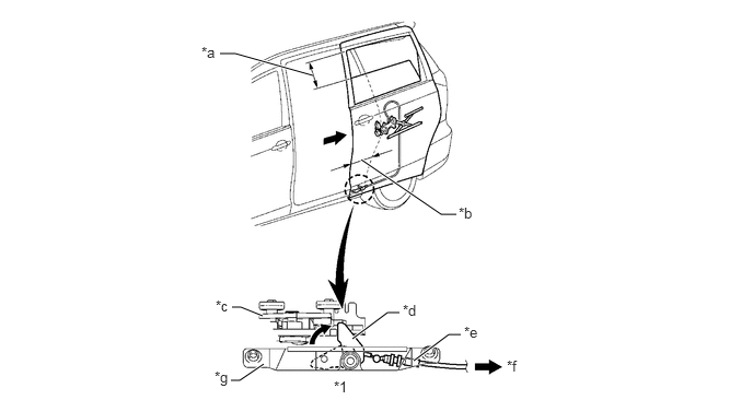
| *1 | Half Open Stopper Assembly | - | - |
| *a | Approximately 100 to 150 mm (0.39 in. to 0.59 in.) or more | *b | Approximately 95 mm (0.37 in.) |
| *c | Slide Door | *d | Hook |
| *e | Slide Door Control Cable | *f | To Power Window |
| *g | Base | - | - |
Operation with Fuel Lid Open
If the slide door is opened while the fuel lid is open, the fuel lid could become damaged. For this reason, if the slide door is opened while the fuel lid is open, it cannot be operated automatically. At the time, the slide door of right side can operate automatically.
Jam Protection Function
Jam Protection by Hall IC
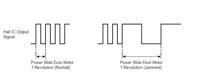
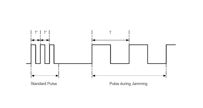
If an object is jammed during the operation of the slide door, the power slide door ECU detects a change in the width of the pulses that are output by the Hall ICs of the power slide door motor. If the power slide door ECU receives pulse fluctuations during the opening or closing operation of the slide door, it sounds the power slide door warning buzzer for 0.1 seconds, and retracts the slide door. The detection of the overload is corrected at predetermined intervals in accordance with the changes in the speed of the motor (the moving speed of the slide door).
Jam Protection by Touch Sensor
If the touch sensor that is provided at the front end of the slide door becomes compressed due to the jamming of an object while the slide door is moving in the closing direction, the resistance of the sensor changes. When the ON signal of the touch sensor is input in the power slide door ECU, the close relay turns OFF to cut off the current that was flowing in the closing direction, thus stopping the power slide door motor. After the power slide door warning buzzer sounds for approximately 0.1 seconds, the open relay turns ON to operate the power slide door motor in reverse, in the opening direction.
Continuous Jamming Detected
If the power slide door ECU detects two consecutive jamming in a slide door operation, in the next instant, the ECU turns OFF the power slide door control motor and the magnetic clutch. As a result, the slide door can be operated manually.
The operating condition of the jam protection function has been changed from 2 consecutive jam detections in one operation direction of the power slide door to 2 consecutive jam detections regardless of a power slide door operation direction.
CONSTRUCTION
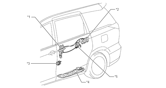
| *1 | Power Slide Door Lock Remote Control Assembly | *2 | Power Slide Door Lock Assembly |
| *3 | Power Slide Door Front Lock Assembly | *4 | Power Slide Door Motor
·
Power Slide Door ECU |
| *5 | Power Slide Door Lock Release Motor Assembly | - | - |
Power Slide Door Drive Unit
The power slide door motor rotates the main pulley, which drives the power slide door drive belt. This allows the slide door to operate via a bracket that is provided between the power slide door drive belt and the slide door.
The Hall ICs in the power slide door motor detect the slide door position and the open-close direction, as well as the speed changes that occur when the slide door becomes jammed with an object during an automatic opening or closing operation.
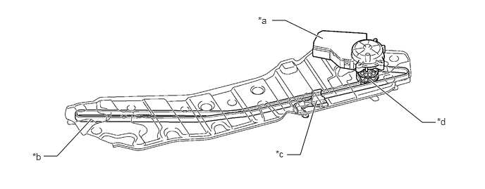
| *a | Power Slide Door Motor
·
Power Slide Door ECU |
*b | Power Slide Door Drive Belt |
| *c | Bracket | *d | Main Pulley |
Touch Sensor
If the touch sensor becomes compressed while the slide door is moving in the closing direction, the built-in pieces of conductive rubber contact each other, causing the resistance of the sensor to change. This change in resistance is output to the power slide door ECU to detect the presence of a jammed object.
| Normal | Jammed |
|---|---|
| Approx. 1 kΩ | Approx. 100 Ω |
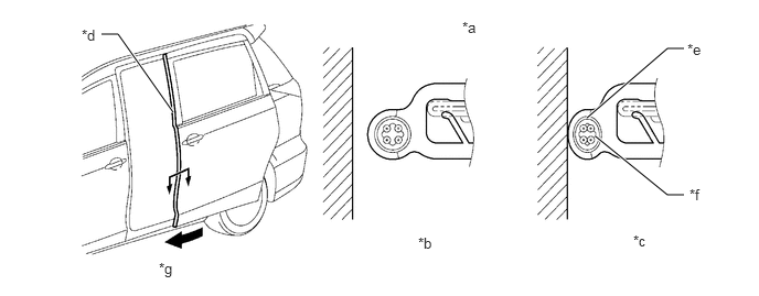
| *a | A-A Cross Section | *b | Normal |
| *c | Jammed | *d | Touch Sensor |
| *e | Conductive Rubber | *f | Core Line |
| *g | Slide Door Closing Direction | - | - |
Power Slide Door Lock Assembly
The power slide door lock assembly fully closes the slide door automatically when the slide door is ajar.
When the rotational movement of the full lock motor is transmitted to the driven gear, the latch turns with the passive lever. Thus, the half latch condition changes to the full latch condition, enabling the slide door that is ajar to become fully closed.
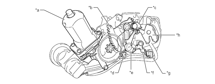
| *a | Full Lock Motor | *b | Driven Gear |
| *c | Passive Lever | *d | Neutral Position Switch |
| *e | Open Lever | *f | Lift Lever |
| *g | Pawl Switch | *h | Latch
·
Latch Switch |
Power Slide Door Lock Remote Control Assembly (With Handle Switch)
The slide door lock remote control assembly is provided with a handle switch. When the inside or outside door handle is operated, the handle switch turns ON, and the resultant signal is output to the power slide door ECU.
When the inside door handle is operated, the control lever No. 4 turns counterclockwise, causing the handle switch to turn ON.
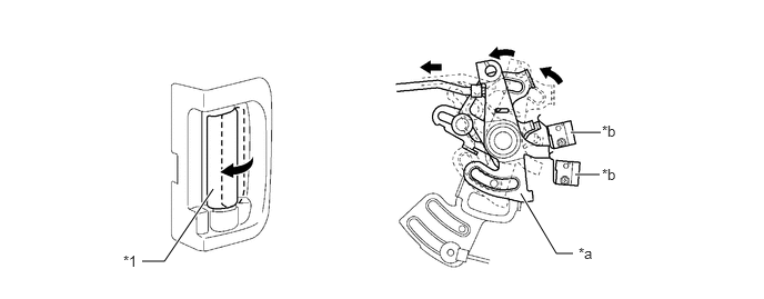
| *1 | Inside Door Handle | - | - |
| *a | Control Lever No.4 | *b | Handle Switch |
When the outside door handle is operated, the control lever No. 2 turns counterclockwise, causing the handle switch to turn ON.
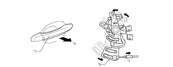
| *1 | Outside Door Handle | - | - |
| *a | Pull | *b | Control Lever No.2 |
| *c | To Outside Door Handle | - | - |
Power Slide Door Lock Release Motor Assembly
When the driver's power slide door switch or transmitter is pressed while the slide door is unlocked and fully closed, the power slide door lock release motor rotates. This rotational movement is transmitted to the power slide door lock remote control assembly and release the latch of it.
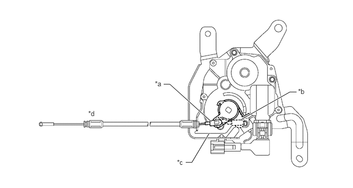
| *a | Lock Position | *b | Unlock Position |
| *c | Power Slide Door Lock Release Motor | *d | To Power Slide Door Lock Remote Control Assembly |
OPERATION
Power Slide Door Drive Unit
The power slide door ECU detects the motor speed by way of the intervals of the pulses that are output by the Hall IC. Accordingly, the power slide door ECU controls the overload detection of the jam protection function by sensing the load that is applied to the slide door.
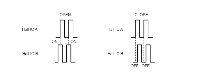
The power slide door ECU detects the amount of movement of the slide door from the phase difference between the pulses from the Hall IC A and Hall IC B.
Power Slide Door Lock Assembly
A cancel system is provided to enable the slide door to be opened by operating the inside or outside handle if an object is jammed while the slide door that is ajar becomes fully closed. If the rotational movement of the full lock motor is interrupted, the slide door can be unlocked by disrupting the actuation transmission path of the full lock motor (by releasing the cancel lever). The mechanism of the cancel system is described below.
Pulling the inside or outside handle pulls on the cable. At this time, the open lever turns counterclockwise, and the lift lever turns clockwise.
The cancel lever, which is synchronized with the open lever, turns counterclockwise. Simultaneously, the passive lever turns counterclockwise. At this time, the latch becomes released.
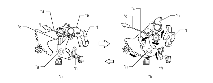
| *a | Fully Locked | *b | Canceled |
| *c | Cancel Lever | *d | Cable |
| *e | Passive Lever | *f | Latch |
| *g | Open Lever | *h | Lift Lever |
| *i | To Inside / Outside Handle | - | - |