K112 CVT CVT SYSTEM GENERAL/CONTROL/DETAILS DETAILS
SYSTEM CONTROL
The main components of the K112 CVT electronic control system are as follows:
| Components | Function | |
|---|---|---|
| ECM | ·
Performs integrated control of the engine and CVT and control of the CVT based on signals from various sensors. ·
When the ECM detects a malfunction, the ECM stores information related to the fault. |
|
| Combination Meter Assembly | Shift Position Indicator Light | Indicates the shift lever position |
| M Mode Indicator Light | Illuminates when the shift lever is in M to inform the driver that M mode is active. | |
| Malfunction Indicator Lamp (MIL) | Illuminates or blinks to alert the driver that the ECM has detected a malfunction. | |
| Solenoid Valve SLS | ·
Controls the hydraulic pressure applied to the secondary pulley in order to control the belt clamping pressure necessary for transmitting torque. ·
Controls the line pressure upon engagement of the forward clutch and reverse brake. |
|
| Solenoid Valve SL | Solenoid valve SL switches the control of the solenoid valve SLS. | |
| Solenoid Valve DS1 | Controls the fluid inflow volume to the primary pulley in accordance with the vehicle speed and accelerator pedal position (speed control during acceleration). | |
| Solenoid Valve DS2 | Controls the fluid outflow volume from the primary pulley in accordance with the vehicle speed and accelerator pedal position (speed control during deceleration). | |
| Solenoid Valve DSU | Controls the engagement hydraulic pressure of the lock-up clutch. | |
| Transmission Revolution Sensor (NIN) | Detects the primary pulley speed (input speed). | |
| Transmission Revolution Sensor (NOUT) | Detects the secondary pulley speed (output speed). | |
| Transmission Revolution Sensor (NT) | Detects the forward clutch drum speed. | |
| CVT Fluid Temperature Sensor | Detects the CVTF temperature. | |
| Oil Pressure Sensor | Detects the steel belt clamping pressure. | |
| Accelerator Pedal Position Sensor | Detects the amount of pedal effort applied to the accelerator pedal. | |
| Throttle Position Sensor | Detects the opening angle of the throttle valve. | |
| Crankshaft Position Sensor | Detects the engine speed. | |
| Engine Coolant Temperature Sensor | Detects the engine coolant temperature. | |
| Yawrate Sensor | Detects the inclination angle of the vehicle. | |
| Park/Neutral Position Switch | Detects the shift lever position. | |
| Transmission Control Switch | Detects if the shift lever is in M. | |
| Stop Light Switch | Detects when the brake pedal is depressed. | |
| Brake Actuator Assembly (Skid Control ECU) | Outputs signals such as the vehicle speed signal and vehicle inclination angle signal to the ECM. | |
The electronic control system of the K112 CVT consists of the controls listed below.
| System | Outline |
|---|---|
|
*1: Input speed is increased, similar to a high gear in a conventional transaxle *2: Input speed is reduced, similar to a low gear in a conventional transaxle |
|
| Engine-CVT Integrated Control | Through communication signals between the ECM and the CVT, the engine-CVT integrated control achieves smooth and powerful driving, and excellent fuel economy. |
| Acceleration Improvement Control (Linear Feeling Improvement Control) | Improves the acceleration feeling by judging the driver's acceleration demand according to the change of vehicle speed and change of accelerator input. |
| Neutral Control | When the vehicle is stopped, the drive force to the transaxle is shut off to improve fuel economy. |
| Uphill/Downhill Shift Control | Controls upshifts*1 and downshifts*2 according to the road slope to obtain smooth acceleration and appropriate engine braking force. |
| Pulley Ratio Control | Controls the primary pulley to obtain the optimum pulley ratio to achieve comfortable driving. |
| Shift and Lock-up Timing Control | The lock-up area is enlarged towards the low vehicle speed range to widen the fuel-cut area. This improves fuel economy. |
| 7-speed Sport Sequential Shiftmatic | Optimally controls the pulley ratio and shifting speed to suit the driver's intentions and driving conditions based on signals from various sensors and switches. |
| Fail-safe | If a malfunction is detected in the sensors or solenoids, the ECM performs fail-safe control to prevent the vehicle's drivability from being significantly affected. |
| Diagnosis | When the ECM detects a malfunction, the ECM stores information related to the fault. |
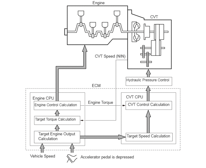
Engine-CVT Integrated Control
To perform fine-tuned control in accordance with driving conditions, various signals are exchanged between the engine CPU and the CVT CPU. As a result, both smooth and powerful driving that excels in ratio change response and fuel economy has been achieved.
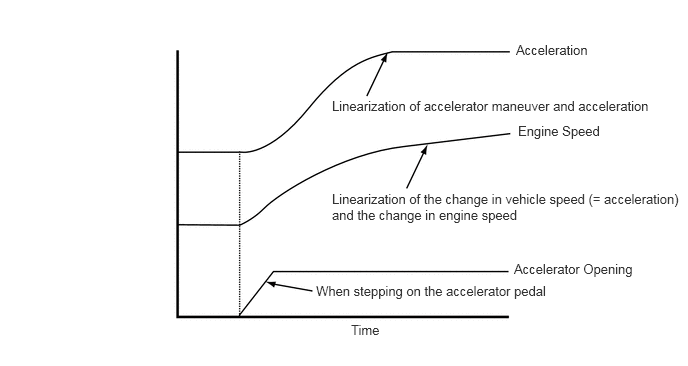
Acceleration Improvement Control (Linear Feeling Improvement Control)
The driver's acceleration demand is judged from the change of vehicle speed and change of accelerator pedal input. When starting off or accelerating, the engine speed and the vehicle speed are controlled to produce a linear feeling, improving the acceleration feeling.
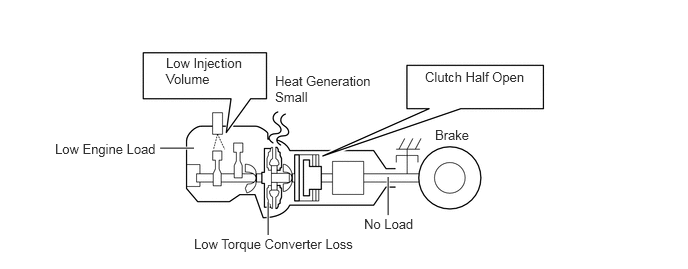
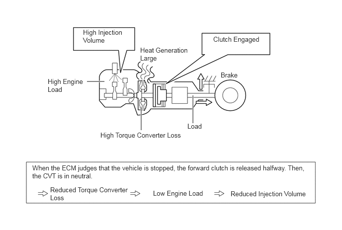
Neutral Control
By disconnecting the engine and the CVT (releasing the forward clutch halfway) while the vehicle is stopped with the shift lever in D, the load on the engine is reduced, improving fuel economy.
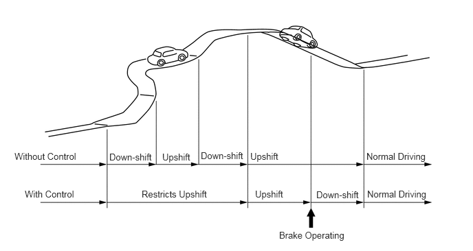
Uphill/Downhill Shift Control
The ECM determines that the vehicle is driving uphill or downhill based on the accelerator pedal position sensor signal and the vehicle speed signal. During uphill driving, it limits upshifts*1 to achieve smooth driving. During downhill driving, it downshifts*2 in order to achieve optimum engine braking.
*1: Selection of a smaller speed ratio
*2: Selects a larger speed ratio
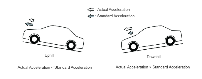
Uphill / downhill grades are judged by comparing the actual acceleration to the standard acceleration memorized in the ECM. When actual acceleration is smaller than the standard acceleration, it is judged to be uphill, and vice versa.
Pulley Ratio Control
The primary pulley speed target is calculated in accordance with accelerator opening, vehicle speed, brake signal, etc. in order to obtain an optimal pulley ratio and ratio change speed, achieving comfortable driving suitable for "driver intention" and " road condition". In order to match the target primary pulley speed and the actual primary pulley speed calculated by the transmission revolution sensor (NIN), the ECM actuates shift solenoid valves DS1 and DS2 in order to control the inflow and outflow volume of line pressure to and from the primary pulley.
When the shift lever is in D, fuel economy and drivability are improved by engine-CVT integrated control.
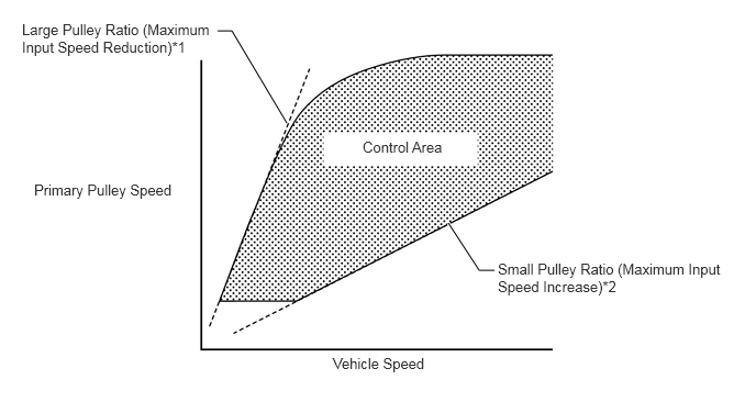
*1: Similar to a low gear in a conventional transaxle
*2: Similar to a high gear in a conventional transaxle
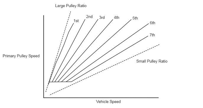
When the shift lever is in M, the shift characteristics are as shown below. The system will upshift automatically when the vehicle reaches a set speed during acceleration.
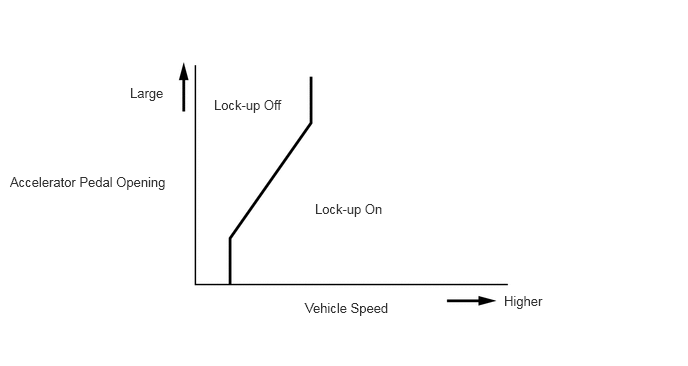
Shift and Lock-up Timing Control
Lock-up is performed based on accelerator pedal opening and vehicle speed. The lock-up area has been enlarged to allow the lock-up to be operated while the vehicle is driving at slower speeds. In addition, the lock-up area is enlarged towards the low vehicle speed range to widen the fuel cut area, improving fuel economy.
7-speed Sport Sequential Shiftmatic
In M mode, by moving the shift lever in the "+" direction or "-" direction, the driver can select the desired shift range. Thus, the driver is able to shift gears with a manual-like feel.
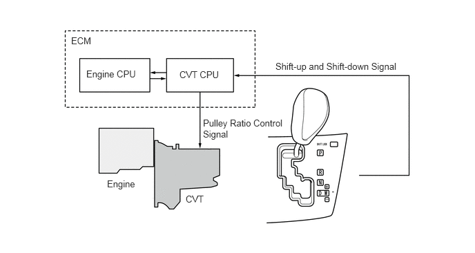
In M mode, the transmission automatically upshifts or downshifts under the following conditions:
| Condition | System Control |
|---|---|
| Engine is under-revving. | 1 step downshift |
| Engine is over-revving. | 1 step upshift |
The ECM will restrict the changing of the shift range if it detects a malfunction in the CVT system.
If the vehicle speed and engine speed exceeds or goes below a preset level in response to the driver's downshift operation request, changing the shift range will be prohibited. In this case, the multi buzzer in the combination meter will sound to alert the driver.
Shift Lock System
The shift lock mechanism prevents the shift lever from being shifted to a position other than P, unless the engine switch is on (IG) and the brake pedal is depressed. This mechanism helps prevent unintentional acceleration.
The shift lock system consists of the shift lock ECU sub-assembly, shift lock solenoid assembly, and a shift lock override button.
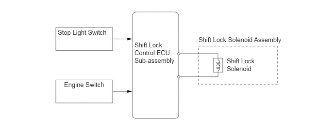
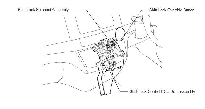
The shift lock control ECU sub-assembly receives inputs from the stop light switch and the engine switch. Upon receiving these signals, the s
A shift lock override button, which manually overrides the shift lock mechanism, is provided.
CONSTRUCTION
CASES
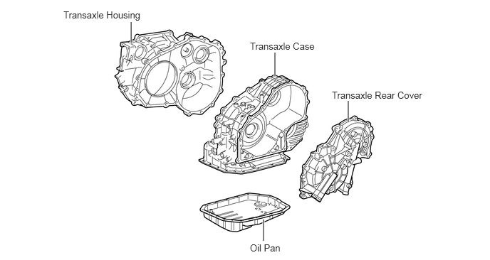
Design of the cases and ribs has been optimized by Finite Element Method (FEM)* analysis, achieving high rigidity, and reducing deformation caused by load from the gear train. Also, aluminum alloy is used for the case and cover to reduce weight.
*: A type of structural analysis that is used for design to achieve good vibration, noise and collision safety performance.
CVT FLUID TC
Toyota genuine CVT Fluid (CVTF) TC is used.
CVTF TC ensures a high coefficient of friction between metals, something that is required for a belt-type CVT. This makes it possible to use lower hydraulic pressures for the pulleys. As a result, high transmission efficiency and the durability of the metal belt have been improved.
TORQUE CONVERTER
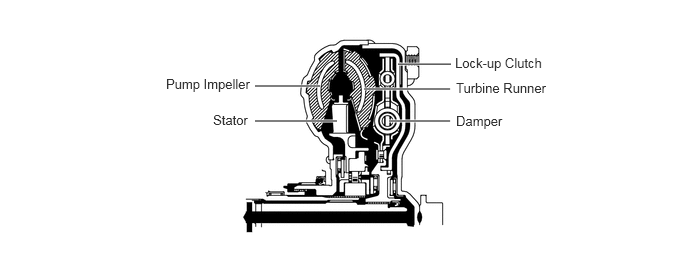
Excellent starting, acceleration and fuel economy are achieved by the use of a torque converter with high transmission efficiency.
A damper structure, which allows lock up operation of the torque converter at lower speeds, is used. This absorbs engine torque fluctuations and provides excellent ride comfort.
Space has been saved by using a small sized, torus-shaped torque converter.
OIL PUMP
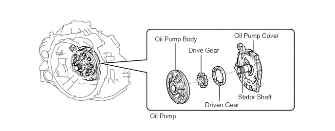
A high-accuracy, high-pressure oil pump is used to improve fuel economy and reduce size.
CVTF WARMER
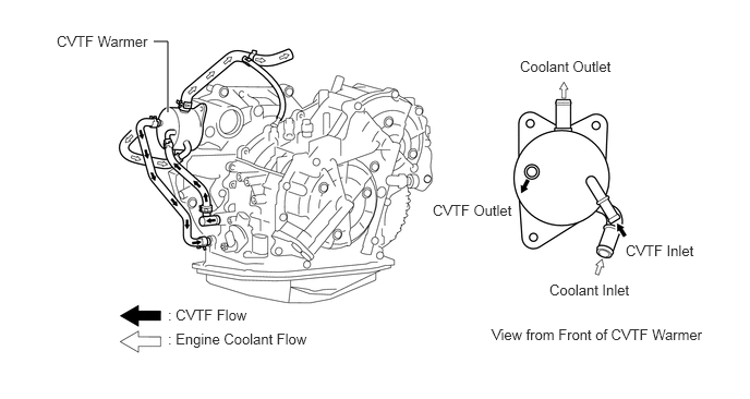
A CVTF warmer is installed instead of the generally used fluid cooler contained in the radiator.
A CVTF warmer increases the warm-up speed of the CVTF and also works as a fluid cooler to reduce CVTF temperature after the fluid has warmed up.
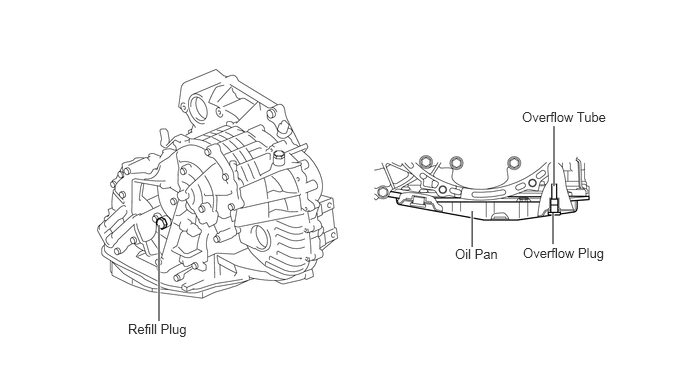
CVTF FILLING PROCEDURE
A special CVTF filling procedure is used in order to improve the accuracy of the CVTF level when CVT is being repaired or replaced. As a result, the oil filler tube and the oil level dipstick used for a conventional automatic transaxle have been discontinued.
This filling procedure uses a refill plug, overflow plug, CVTF temperature sensor, and the shift position indicator light "D". For details, refer to the Repair Manual.
GEAR TRAIN
The torque converter and oil pump are installed on the input shaft, and a planetary gear is installed to enable either forward or reverse.
The gear train has a pulley-belt unit, a reduction drive gear set and a final ring gear set. The pulley ratio is continuously changed by adjusting the diameter of the pulleys that the metal belt is wrapped around.
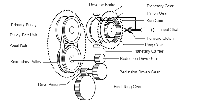
| Component | Function |
|---|---|
| Forward Clutch | Transmits drive force from the engine to the planetary sun gear during forward motion. |
| Reverse Brake | Locks the planetary carrier during reverse motion. |
| Planetary Gear | Switches on and off to change between forward and reverse. |
| Pulley-Belt Unit | Changes the pulley ratio continuously and transmits output from the engine seamlessly. |
| Reduction Gear | Transmits drive force to the differential. |
Pulley and Belt
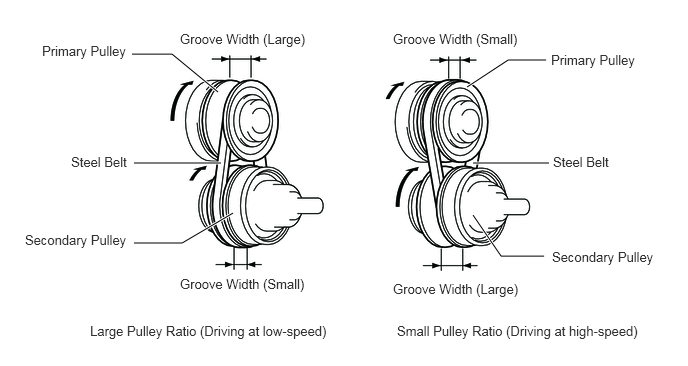
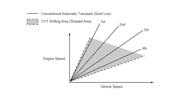
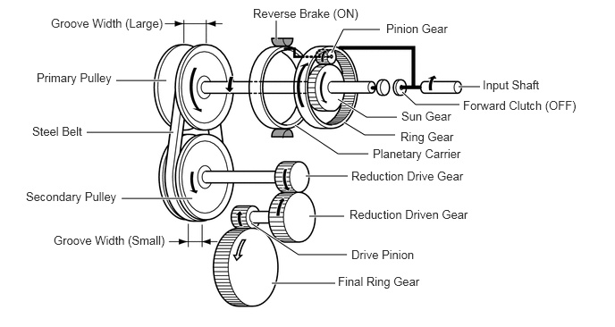
Unlike a conventional automatic transaxle that requires gear changes, the K112 CVT changes the pulley ratio using a pulley-belt unit. The pulley-belt unit consists of pair of pulleys, with a variable groove width that can be freely changed by hydraulic pressure, and a steel-belt that runs between them.
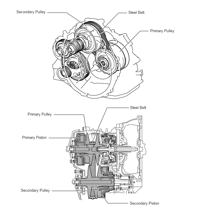
The groove width is adjusted to perform seamless changing of the ratio between the pulleys. Moreover, through the use of a wide pulley ratio range, excellent fuel economy and quietness are ensured.
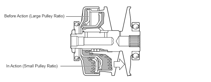
CVT Pulley
chambers positioned in parallel, presses the belt. This pulley structure reduces the outer diameter of the hydraulic pressure chambers and provides a compactly designed system.
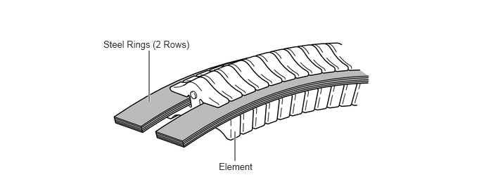
Steel Belt for CVT
The steel belt consists of metallic elements and two rows of steel rings.
In contrast to chains and rubber belts, which transmit power through the use of tensile force, a metallic belt uses the compressive action (pushing force) of the elements to transmit power.
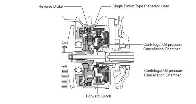
Forward/Backward Switching Unit
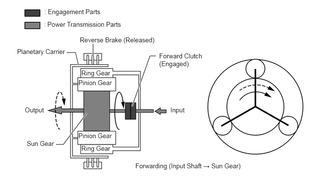
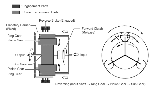
A single pinion planetary gear is used as a switching control mechanism to allow either forward or reverse motion.
This mechanism consists of a reverse brake that locks the planetary carrier and a forward clutch that transmits the engine drive force to the planetary sun gear.
A centrifugal oil-pressure cancellation chamber is situated on the forward clutch to cancel the centrifugal hydraulic pressure generated by the clutch revolution, and improve hydraulic pressure response time.
During forward motion, the forward clutch is engaged. Drive force output from the engine is sent to the pulley-belt unit through the input shaft and sun gear.
During reverse motion, the forward clutch is disengaged and the reverse brake is engaged. This stops the planetary carrier from turning, which stops the orbital revolution of the pinion gear. The drive force input from the engine is transmitted to the ring gear, and then to the sun gear through the pinion gears. The rotation direction of the drive force from the engine is reversed and then this drive force is output to the pulley-belt unit.
Reduction Gear and Differential
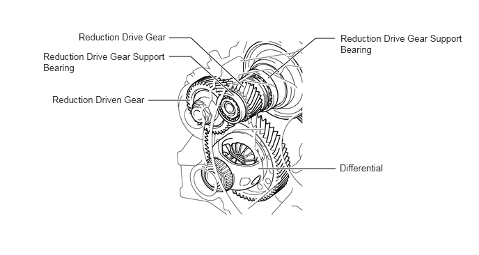
The reduction gear reduces the speed output from the pulley-belt unit and transmits it to the differential drive pinion.
Two independent bearings support the reduction drive gear to enable optimal engagement with the driven gear. This provides a significant reduction in noise.
The two-pinion type front differential uses helical gears as the reduction mechanism and straight bevel gears as the differential gear mechanism.
PARKING LOCK MECHANISM
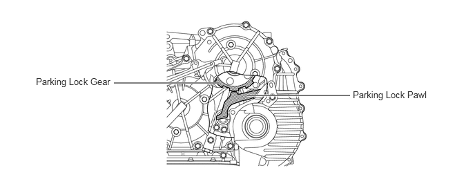
The parking lock gear is attached to the secondary pulley. When the shift lever is moved to "P", the transmission control lever activates and the manual valve lever shaft turns the manual valve lever to move the parking lock rod. This engages the parking lock pawl with the parking lock gear and locks the movement of the vehicle.
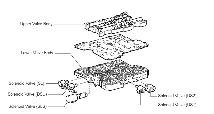
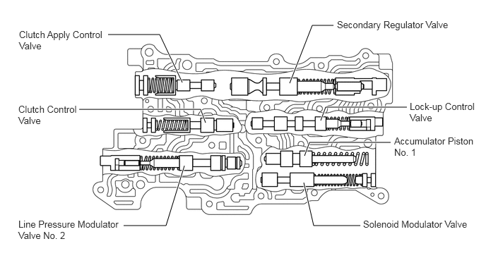
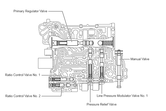
VALVE BODY UNIT
The valve body unit consists of the upper valve body, the lower valve body and 5 solenoid valves (DS1, DS2, SL, DSU, SLS).
The rigidity of the valve body has been improved to enable it to be used when higher hydraulic pressures are applied. Moreover, the 5 solenoid valves are installed in the lower valve body to ensure serviceability.
Solenoid Valve SLS
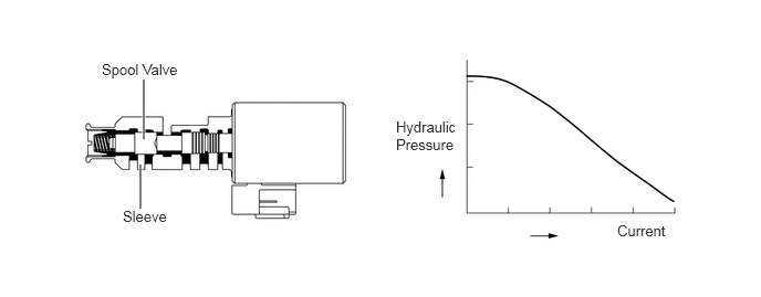
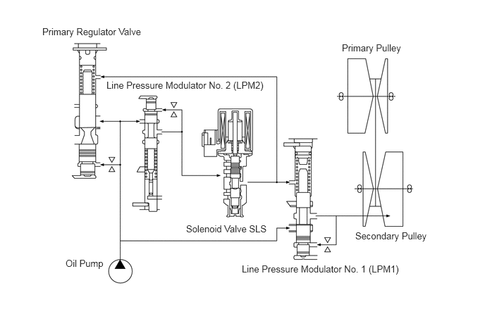
The SLS solenoid valve is a linear solenoid valve used to control the belt clamping pressure.
By using a linear solenoid valve to control the hydraulic pressure, the groove width relationship of the secondary pulley and primary pulley can be maintained at all times.
When the forward clutch or reverse brake is engaging, or the neutral control is operated, the SLS solenoid valve controls the hydraulic pressure applied to the forward clutch or reverse brake
Solenoid Valves DS1, DS2, SL and DSU
The DS1 and DS2 solenoid valves are used for primary pulley control, the SL solenoid valve is used for selecting the usage of solenoid valve SLS, and the DSU solenoid valve is used for finely adjusting the hydraulic pressure used to engage the lock-up clutch.
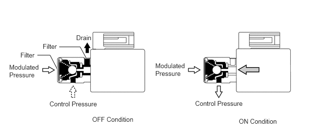
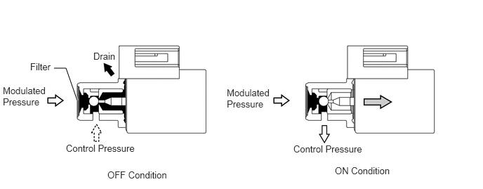
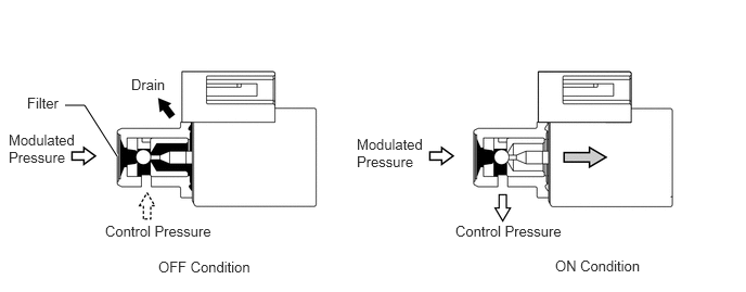
| Solenoid Valve | Function |
|---|---|
| DS1 | Controls the fluid flow volume to the primary pulley according to the vehicle speed and accelerator opening. Controls the acceleration |
| DS2 | Controls the fluid flow volume from the primary pulley according to the vehicle speed and accelerator opening. Controls the deceleration. |
| SL | or disables switching the usage of solenoid valve SLS. |
| DSU | Controls the hydraulic pressure for the lock-up clutch. |
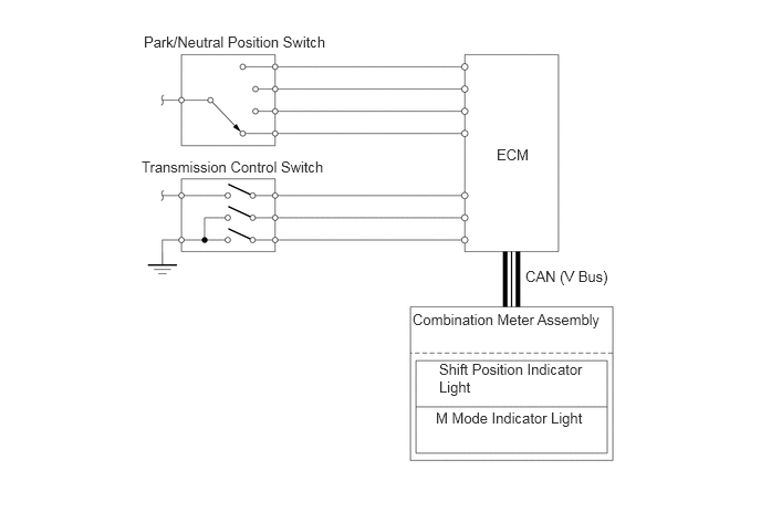
Park/Neutral Position Switch and Transmission Control Switch
The ECM uses these switches to detect the shift lever position.
The park/neutral position switch sends the P, R, N and D position signals to the ECM.
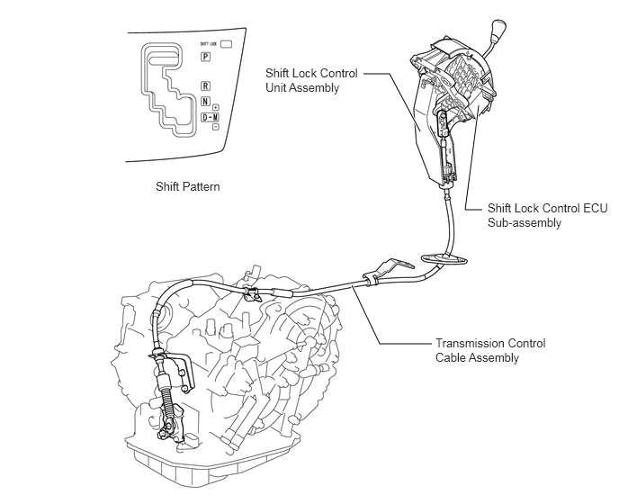
The transmission control switch is installed inside the shift lock control unit. This switch sends M position signals to the ECM.
SHIFT CONTROL MECHANISM
A gate type shift lever with a transmission control cable is used.
The shift control mechanism uses a push-pull cable.
The shift lever unit uses a gate type shift lever that is located on the instrument panel.
A shift unlock button is provided on the shift lever housing section for use in the event of an emergency.
A shift pattern with M located to the side of D is provided.
OPERATION
Transaxle Power Flow
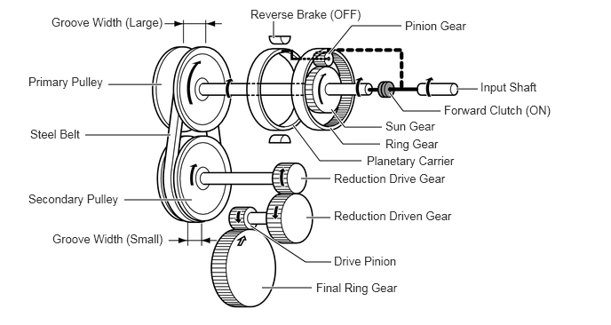
*1: Similar to a low gear in a conventional transaxle
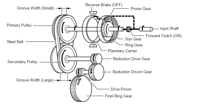
*2: Similar to a high gear in a conventional transaxle
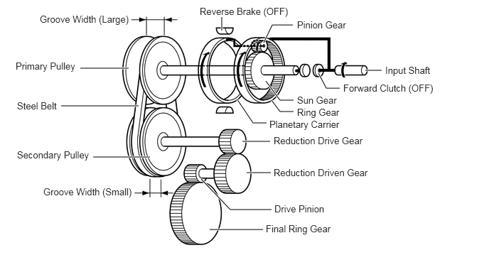
Belt Clamping Pressure Control Mechanism
An appropriate amount of belt clamping pressure is necessary for transmitting torque. The belt clamping pressure is controlled by the secondary pulley hydraulic pressure. A pressure control valve and solenoid valve are installed on the downstream side of the line pressure, which are both used exclusively for controlling belt clamping pressure. This has made it possible to optimize the hydraulic pressure used to control the belt clamping force.
Pulley Ratio Control Mechanism
Pulley ratio control is performed by controlling the inflow and outflow of the CVTF to or from the primary pulley.
By computerizing this control, pulley ratio control can be more flexible, and provides drivers with excellent control. Moreover, it becomes possible to set the pulley ratio and shift speed close to the optimal fuel economy line of the engine control. Separate hydraulic circuits are provided for changing the ratio to a smaller pulley ratio*1 and for changing to a larger pulley ratio*2 in order to provide fine-tuned control and a high level of reliability. The ratio is changed to a smaller pulley ratio by controlling fluid inflow, and changed to a larger pulley ratio by controlling fluid outflow.
*1: Input speed is increased, similar to a high gear in a conventional transaxle
*2: Input speed is reduced, similar to a low gear in a conventional transaxle
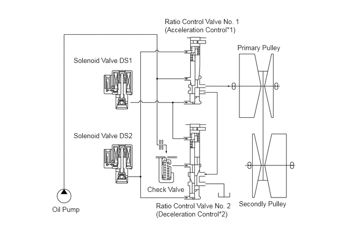
*1: Input speed is increased, similar to a high gear in a conventional transaxle
*2: Input speed is reduced, similar to a low gear in a conventional transaxle
FAIL-SAFE
This function minimizes the loss of operability when an abnormality occurs in a sensor or solenoid. For details, refer to the Repair Manual.
| Malfunction Part | Function |
|---|---|
| Transmission Revolution Sensor (NIN) | Input speed is calculated based on the transmission revolution sensor (NT) signal and normal control is performed. |
| Transmission Revolution Sensor (NOUT) | Output speed is calculated based on the vehicle speed signal and normal control is performed. |
| Transmission Revolution Sensor (NT) | The turbine speed is calculated based on the transmission revolution sensor (NIN) signal and normal control is performed. |
| Solenoid Valve SLS | ·
During a solenoid valve SLS malfunction, the current to solenoid valve SLS is stopped and the belt clamping pressure is maintained by the line pressure. ·
The pulley ratio is fixed at a predetermined value. |
| Solenoid Valve SL | During a solenoid valve SL malfunction, the current to solenoid valve SL is stopped and the lock-up clutch is released. |
| Solenoid Valve DS1 | During a solenoid valve DS1 malfunction, the current to solenoid valve DS1 is stopped, causing the pulley ratio to lean more towards a speed reduction ratio than normal. |
| Solenoid Valve DS2 | During a solenoid valve DS2 malfunction, the current to solenoid valve DS2 is stopped, causing the pulley ratio to lean more towards a speed increase ratio than normal. |
| Solenoid Valve DSU | During a solenoid valve DSU malfunction, the current to solenoid valve DSU is stopped and the lock-up clutch is released. |
| CVT Fluid Temperature Sensor | During a CVT fluid temperature sensor malfunction, the ECM uses a predetermined fluid temperature and performs normal control. |
| Yawrate Sensor | Neutral control is disabled when a malfunction is detected |
DIAGNOSIS
When the ECM detects a malfunction, the ECM records information related to the fault. Furthermore, the Malfunction Indicator Lamp (MIL) in the combination meter illuminates or blinks to inform the driver of the malfunction.
At the same time, Diagnosis Trouble Codes (DTCs) are stored in memory. The DTCs stored in the ECM can be read by connecting the intelligent tester to the DLC3. For details, refer to the Repair Manual.