Home › Engine / Hybrid System › 2AZ-FE ENGINE MECHANICAL › ENGINE UNIT
NM24M0E _51 Engine / Hybrid System _061720 2AZ-FE ENGINE MECHANICAL _0301072 ENGINE UNIT UN GENERAL/CONTROL/DETAILS F

2AZ-FE ENGINE MECHANICAL  ENGINE UNIT  GENERAL/CONTROL/DETAILS  DETAILS  


CONSTRUCTION


a.

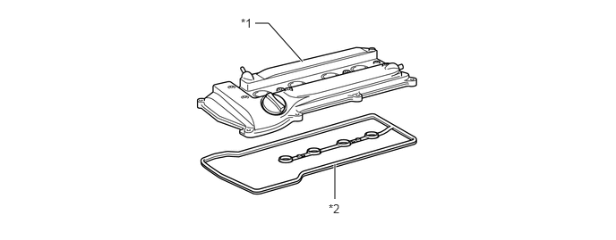
Cylinder Head Cover

i.

A lightweight magnesium alloy die-cast cylinder head cover is used.


ii.

Acrylic rubber, which excels in heat resistance and reliability, is used for the cylinder head cover gasket.
W135191C01
2.969,0.271 3.125,0.271 3.125,0.271 3.521,0.719 true 3.896,2.323 3.896,1.917 true 2.802,0.188 3.115,0.344 0.313,0.156 10 false *1 3.823,2.354 4.135,2.51 0.313,0.156 10 false *2
*1 Cylinder Head Cover *2 Cylinder Head Cover Gasket


b.

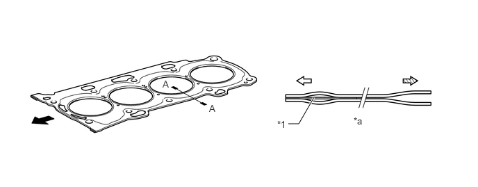
Cylinder Head Gasket

i.

A steel-laminate type cylinder head gasket is used. A shim has been added around the cylinder bore to increase the sealing surface, thus improving the sealing performance and durability.
W101864C01
4.323,1.854 4.479,1.854 4.479,1.854 4.708,1.458 true 3.135,1.542 3.417,1.833 0.281,0.292 10 false A 2.438,1.177 2.719,1.469 0.281,0.292 10 false A 5.302,1.729 5.583,2.021 0.281,0.292 10 false *a 4.156,1.781 4.438,2.073 0.281,0.292 10 false *1
*1 Shim - -
*a A-A Cross Section - -
V100135

Front
V100136

Cylinder Bore Side
V100137

Outer Side - -


c.

Cylinder Head

i.

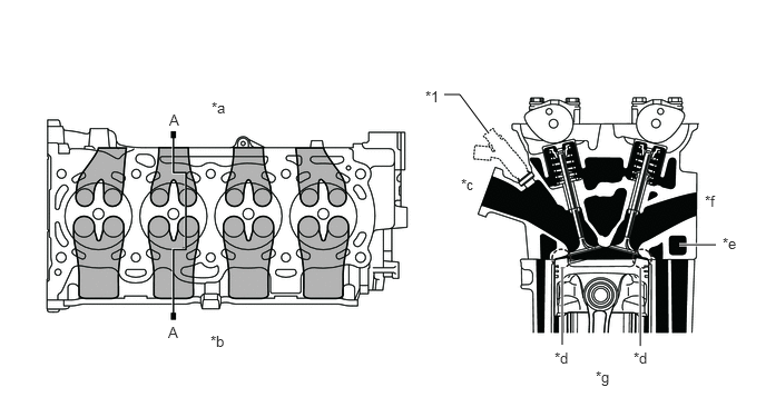
Through the adoption of the taper squish combustion chamber, the engine knocking resistance and fuel efficiency have been improved.


ii.

An upright intake port is used to improve the intake efficiency.


iii.

Installing the injectors in the cylinder head enables the injectors inject fuel as close as possible to the combustion chamber. This prevents the fuel from adhering to the intake port walls, which reduces HC exhaust emissions.


iv.

The routing of the water jacket in the cylinder head has been optimized to realize the high cooling performance. In addition, a water bypass passage has been provided below the exhaust ports to reduce the number of parts and the weight.
W135565C01
6.354,2.292 6.698,2.292 true 5.26,3.229 5.26,2.5 true 5.99,3.24 5.99,2.51 true 4.156,0.885 4.302,0.885 4.302,0.885 4.573,1.25 true 3.979,0.823 4.292,0.979 0.313,0.156 10 false *1 1.583,1.042 1.896,1.198 0.313,0.156 10 false A 1.979,0.927 2.292,1.083 0.313,0.156 10 false *a 1.969,3.115 2.281,3.271 0.313,0.156 10 false *b 6.76,2.198 7.094,2.396 0.333,0.198 10 false *e 6.594,1.802 6.906,1.958 0.313,0.156 10 false *f 1.573,3.031 1.885,3.188 0.313,0.156 10 false A 5.188,3.271 5.5,3.427 0.313,0.156 10 false *d 4.313,1.646 4.625,1.802 0.313,0.156 10 false *c 5.927,3.271 6.271,3.49 0.344,0.219 10 false *d 5.573,3.448 6,3.688 0.427,0.24 10 false *g
*1 Injector - -
*a Exhaust Side *b Intake Side
*c IN *d Taper Squish
*e Water Bypass Passage *f EX
*g A-A Cross Section - -


d.

Cylinder Block

i.

Lightweight aluminum alloy is used for the cylinder block.


ii.

By producing the thin cast-iron liners and cylinder block as a unit, compaction is realized.


iii.

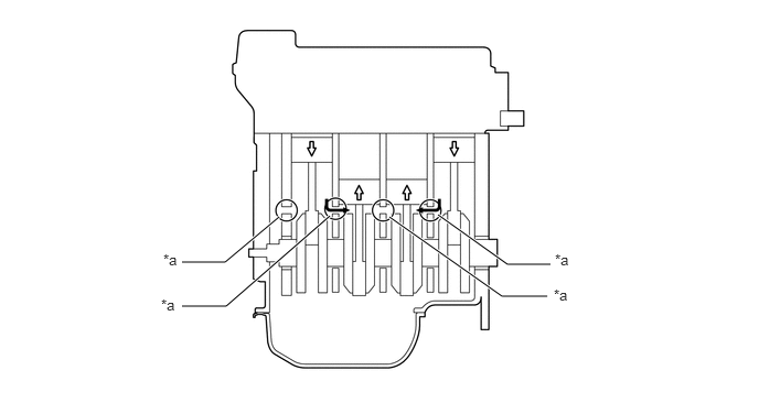
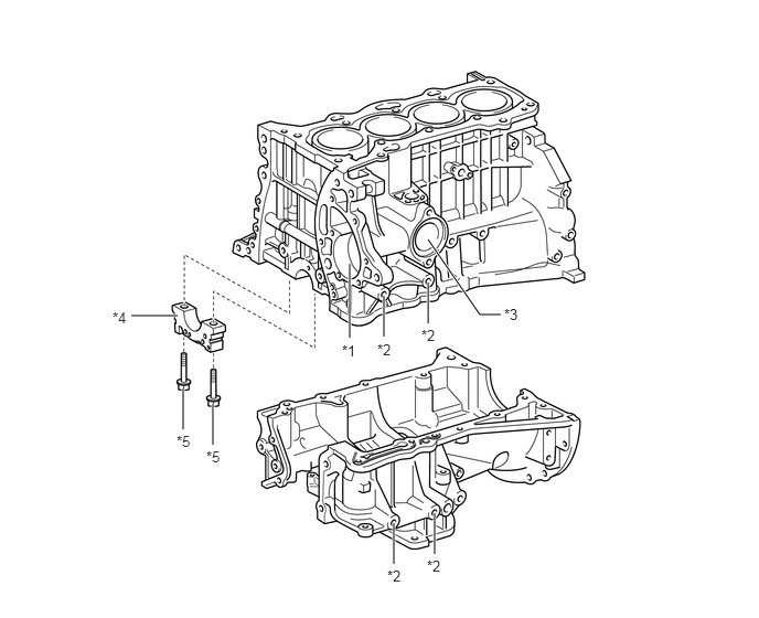
Air passage holes are provided in the crankshaft bearing area of the cylinder block. As a result, the air at the bottom of the cylinder flows smoother, and pumping loss (back pressure at the bottom of the piston generated by the piston's reciprocal movement) is reduced to improve the engine's output.


iv.

The oil filter and the air conditioner compressor brackets are integrated into the crankcase. Also, the water pump swirl chamber and thermostat housing are integrated into the cylinder block.
W135142C01
3.302,3.188 3.302,2.49 true 3.625,3.177 3.625,2.792 true 4.042,3.052 4.042,2.667 true 3.719,5.323 3.719,4.938 true 4.104,5.229 4.104,4.844 true 1.729,4.052 1.729,3.667 true 2.01,4.198 2.01,3.813 true 1.677,2.979 1.24,2.979 true 4.729,2.969 4.531,2.969 4.531,2.969 4.042,2.26 true 3.229,3.229 3.542,3.438 0.313,0.208 10 false *1 3.563,3.219 3.875,3.375 0.313,0.156 10 false *2 4.76,2.885 5.083,3.083 0.323,0.198 10 false *3 1.063,2.917 1.396,3.146 0.333,0.229 10 false *4 1.667,4.083 1.979,4.26 0.313,0.177 10 false *5 3.979,3.083 4.323,3.281 0.344,0.198 10 false *2 1.948,4.229 2.26,4.427 0.313,0.198 10 false *5 3.656,5.354 3.969,5.51 0.313,0.156 10 false *2 4.031,5.26 4.344,5.417 0.313,0.156 10 false *2
*1 Water Pump Swirl Chamber *2 Air Conditioner Compressor Compressor Bracket
*3 Thermostat Housing *4 Crankshaft Bearing Cap
*5 Plastic Region Tightening Bolt - -


Air Flow During Engine Revolution
W135566C01
1.719,2.479 2.125,2.479 2.125,2.479 2.635,2.052 true 1.719,2.896 2.135,2.896 2.135,2.896 3.115,2.042 true 3.677,2.052 4.74,2.802 4.74,2.802 5.167,2.802 true 4.135,2.031 4.792,2.5 4.792,2.5 5.198,2.5 true 1.542,2.375 1.854,2.573 0.313,0.198 10 false *a 1.521,2.802 1.833,3 0.313,0.198 10 false *a 5.24,2.375 5.552,2.573 0.313,0.198 10 false *a 5.229,2.708 5.542,2.906 0.313,0.198 10 false *a
*a Air Passage Hole - -
V100135

Air Flow - -


NOTICE:

Never attempt to machine the cylinder because it has a thin liner thickness.


v.

The liners are the spiny-type, which have been manufactured so that their casting exteriors form large irregular surfaces in order to enhance the adhesion between the liners and the aluminum cylinder block. The enhanced adhesion helps heat dissipation, resulting in a lower overall temperature and heat deformation of the cylinder bores.
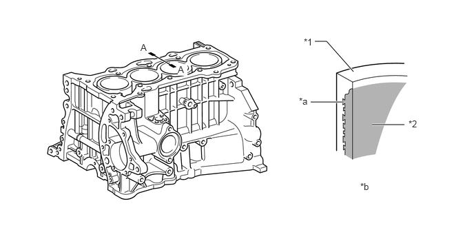
W101867C01
5.625,1.885 6.115,1.885 true 4.76,0.625 4.938,0.625 4.938,0.625 5.344,1.083 true 4.698,1.542 5.188,1.542 true 4.594,0.552 4.948,0.792 0.354,0.24 10 false *1 6.177,1.792 6.49,1.948 0.313,0.156 10 false *2 4.521,1.448 4.833,1.604 0.313,0.156 10 false *a 5.448,2.74 5.76,2.896 0.313,0.156 10 false *b 2.125,0.635 2.49,0.844 0.365,0.208 10 false A 2.688,0.969 2.833,1.146 0.146,0.177 10 true A
*1 Cylinder Block *2 Liner
*a Irregularly shaped outer casting surface of liner *b A-A Cross Section


vi.

Water jacket spacer is provided in the water jacket of the cylinder block.


vii.

They suppress the water flow in the center of the water jackets, guide the water above and below the cylinder bores, and ensure uniform temperature distribution. As a result, the viscosity of the engine oil that acts as a lubricant between the bore walls and the pistons can be lowered, thus reducing friction.
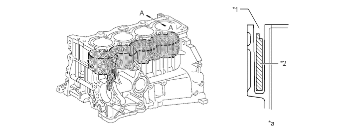
W135164C01
5.427,1.333 5.813,1.333 true 5.01,0.188 5.188,0.188 5.188,0.188 5.417,0.594 true 4.854,0.115 5.188,0.375 0.333,0.26 10 false *1 5.854,1.24 6.167,1.396 0.313,0.156 10 false *2 5.604,2.49 5.917,2.646 0.313,0.156 10 false *a 2.917,0.188 3.083,0.344 0.167,0.156 10 false A 3.521,0.49 3.688,0.646 0.167,0.156 10 true A
*1 Water Jacket *2 Water Jacket Spacer
*a A-A Cross Section - -


e.

Piston

i.

The piston is made of aluminum alloy and skirt area is made compact and lightweight.


ii.

The piston head portion uses a taper squish shape to improve the fuel combustion efficiency.


iii.

The piston skirt has been coated with resin to reduce the friction loss.
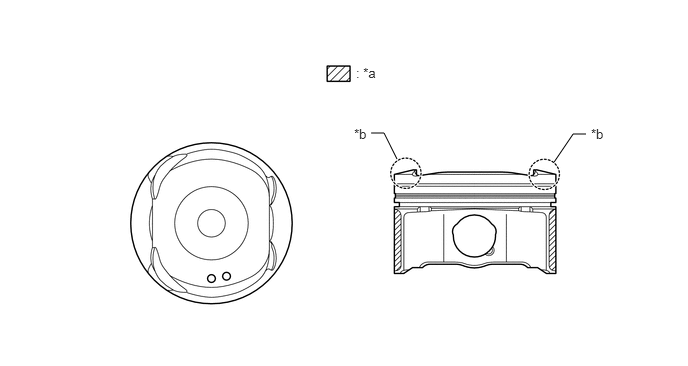
W135567C01
3.865,1.385 4,1.385 4,1.385 4.135,1.656 false 5.771,1.688 5.969,1.396 5.969,1.396 6.104,1.396 false 3.708,0.677 4.021,0.833 0.313,0.156 10 false : *a 3.688,1.313 4,1.469 0.313,0.156 10 false *b 6.156,1.313 6.531,1.604 0.375,0.292 10 false *b
*a Resin Coating *b Taper Squish Shape


f.

Connecting Rod

i.

The connecting rods and caps are made of high-strength steel for weight reduction.


ii.

Nut-less type plastic region tightening bolts are used on the connecting rod for a lighter design.


iii.

The connecting rod bearings are reduced in width to reduce friction.
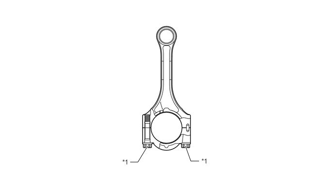
W135181C01
2.792,3.49 2.958,3.49 2.958,3.49 3.167,3.146 true 3.979,3.146 4.094,3.469 4.094,3.469 4.271,3.469 true 2.625,3.406 2.938,3.604 0.313,0.198 10 false *1 4.323,3.385 4.635,3.583 0.313,0.198 10 false *1
*1 Plastic Region Tightening Bolt - -


g.

Crankshaft

i.

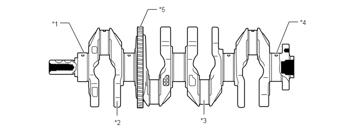
The forged crankshaft has 5 journals and 8 balance weights.


ii.

The crankshaft is made of forged steel.


iii.

Pin and journal fillets are roll-finished to maintain adequate strength.


iv.

The balance shaft drive gear is provided the crankshaft.
W135144C01
2.438,2.417 2.438,2.115 true 4.25,2.396 4.25,2.094 true 1.75,1.104 1.438,0.479 1.438,0.479 1.25,0.479 true 6.208,0.458 6.021,0.458 6.021,0.458 5.75,1.135 true 3.271,0.198 3.083,0.198 3.083,0.198 2.906,0.594 true 1.083,0.417 1.406,0.625 0.323,0.208 10 false *1 2.385,2.479 2.698,2.635 0.313,0.156 10 false *2 4.177,2.438 4.49,2.594 0.313,0.156 10 false *3 6.25,0.385 6.563,0.542 0.313,0.156 10 false *4 3.313,0.115 3.625,0.271 0.313,0.156 10 false *5
*1 No. 1 Journal *2 Balance Weight
*3 Crankshaft Pin *4 Oil Hole
*5 Balance Shaft Drive Gear - -


h.

Balance Shaft

i.

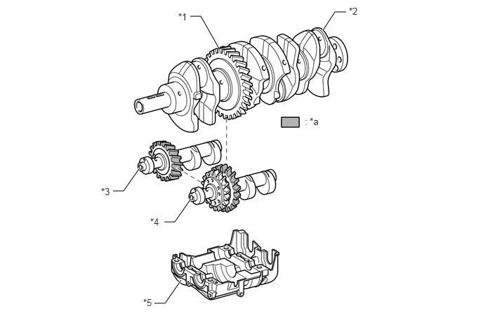
A balance shaft is used to reduce vibrations.


ii.

The crankshaft directly drives the No. 1 balance shaft.


iii.

In addition, a resin gear is used on the driven side to suppress noise and offer lightweight design.
W135145C01
2.823,0.24 2.979,0.24 2.979,0.24 3.25,0.719 true 4.792,0.448 4.969,0.177 4.969,0.177 5.135,0.177 true 2.292,4.5 2.448,4.5 2.448,4.5 2.688,4.156 true 1.677,2.833 1.833,2.833 1.833,2.833 2.073,2.49 true 2.438,3.292 2.594,3.292 2.594,3.292 2.833,2.948 true 2.646,0.167 2.969,0.469 0.323,0.302 10 false *1 5.177,0.083 5.521,0.313 0.344,0.229 10 false *2 1.5,2.76 1.813,2.917 0.313,0.156 10 false *3 2.229,3.208 2.542,3.365 0.313,0.156 10 false *4 2.125,4.406 2.438,4.563 0.313,0.156 10 false *5 4.521,1.719 4.833,1.875 0.313,0.156 10 false : *a
*1 Balance Shaft Drive Gear *2 Crankshaft
*3 No. 2 Balance Shaft *4 No. 1 Balance Shaft
*5 Balance Shaft Housing - -
*a Resin Gear - -


iv.

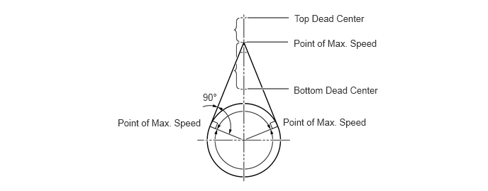
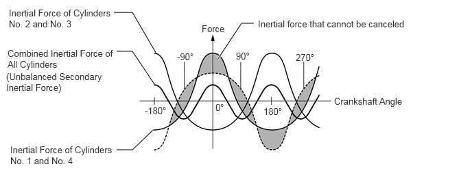
In the in-line 4-cylinder engine, the crankshaft angle for cylinders No. 1 and No. 4 are exactly at the opposite (180°) position of cylinders No. 2 and No. 3. Therefore, the inertial force of the pistons and the connecting rods of the former 2 cylinders and of the latter 2 cylinders almost cancel each other. However, because the position at which the piston reaches its maximum speed is located toward the top dead center from the center of the stroke, the upward inertial force is greater than the downward inertial force. This unbalanced secondary inertial force is generated twice for each rotation of the crankshaft.
W135186E01
3.635,0.26 4.24,0.26 true 3.625,0.615 4.229,0.615 true 3.635,1.302 4.24,1.302 true 4.323,0.188 5.604,0.531 1.281,0.344 10 false Top Dead Center 4.313,0.552 5.594,0.896 1.281,0.344 10 false Point of Max. Speed 4.313,1.24 5.594,1.583 1.281,0.344 10 false Bottom Dead Center 4.156,1.708 5.438,2.052 1.281,0.344 10 false Point of Max. Speed 1.729,1.719 3.01,2.063 1.281,0.344 10 false Point of Max. Speed 2.979,1.344 3.344,1.667 0.365,0.323 10 false 90°

Inertial Force Generated by the In-line 4 Cylinders
W135187E01
3.302,0.906 3.667,0.354 3.667,0.354 3.854,0.354 true 1.729,0.188 2.01,0.188 2.01,0.188 2.365,0.802 true 1.771,0.781 2.01,0.781 2.01,0.781 2.344,1.281 true 1.771,2.281 2.01,2.281 2.01,2.281 2.323,1.979 true 2.688,0.781 3.042,1.063 0.354,0.281 10 false -90° 3.583,0.771 3.938,1.052 0.354,0.281 10 false 90° 3.271,1.552 3.625,1.833 0.354,0.281 10 false 0° 4,1.615 4.354,1.896 0.354,0.281 10 false 180° 4.49,0.792 4.844,1.073 0.354,0.281 10 false 270° 2.198,1.604 2.552,1.885 0.354,0.281 10 false -180° 3.063,0.354 3.552,0.604 0.49,0.25 10 false Force 5.073,1.458 6.208,1.823 1.135,0.365 10 false Crankshaft Angle 3.917,0.281 6.25,0.573 2.333,0.292 10 false Inertial force that cannot be canceled 0.135,0.115 1.708,0.573 1.573,0.458 10 false Inertial Force of Cylinders No. 2 and No. 3 0.115,0.729 1.75,1.094 1.635,0.365 10 false Combined Inertial Force of All Cylinders 0.094,1.083 1.583,1.469 1.49,0.385 10 false (Unbalanced Secondary Inertial Force) 0.156,2.198 1.729,2.656 1.573,0.458 10 false Inertial Force of Cylinders No. 1 and No. 4


v.

To cancel the unbalance secondary inertial force, 2 balance shafts are rotated twice for each rotation of the crankshaft and generate inertial force in the opposite direction. Also, in order to cancel the inertial force generated by the balance shaft itself, the balance shaft actually consists of 2 shafts rotating in opposite directions.
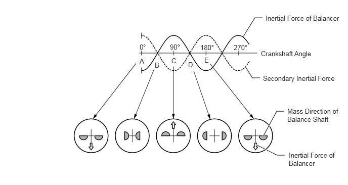
Mass Direction of Balance Shaft at Crankshaft Angle
W135188E01
5.01,0.75 5.25,0.365 5.25,0.365 5.406,0.365 true 5.052,1.375 5.198,1.604 5.198,1.604 5.354,1.604 true 5.417,2.813 5.698,2.292 5.698,2.292 5.854,2.292 true 5.271,2.979 5.708,3.198 5.708,3.198 5.865,3.198 true 2.875,0.885 3.25,1.177 0.375,0.292 10 false 0° 3.5,0.885 3.875,1.177 0.375,0.292 10 false 90° 4.125,0.896 4.5,1.188 0.375,0.292 10 false 180° 4.813,0.896 5.188,1.188 0.375,0.292 10 false 270° 2.875,1.177 3.125,1.49 0.25,0.313 10 false A 3.188,1.26 3.438,1.573 0.25,0.313 10 false B 3.531,1.167 3.781,1.479 0.25,0.313 10 false C 3.875,1.25 4.125,1.563 0.25,0.313 10 false D 4.208,1.156 4.458,1.469 0.25,0.313 10 false E 5.375,1.021 6.542,1.417 1.167,0.396 10 false Crankshaft Angle 5.469,0.292 7.083,0.74 1.615,0.448 10 false Inertial Force of Balancer 5.417,1.531 7.031,1.979 1.615,0.448 10 false Secondary Inertial Force 5.917,2.208 7.021,2.719 1.104,0.51 10 false Mass Direction of Balance Shaft 5.948,3.115 6.938,3.656 0.99,0.542 10 false Inertial Force of Balancer


i.

Valve Mechanism

i.

The VVT-i system is used to improve fuel economy, engine performance and reduce exhaust emissions.


ii.

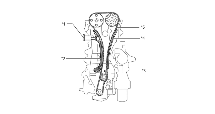
The intake and exhaust camshafts are driven by a timing chain.


iii.

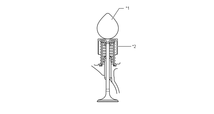
Along with the increase in the amount of valve lift, the shim-less type valve lifter is used. This valve lifter increases the cam contact surface.
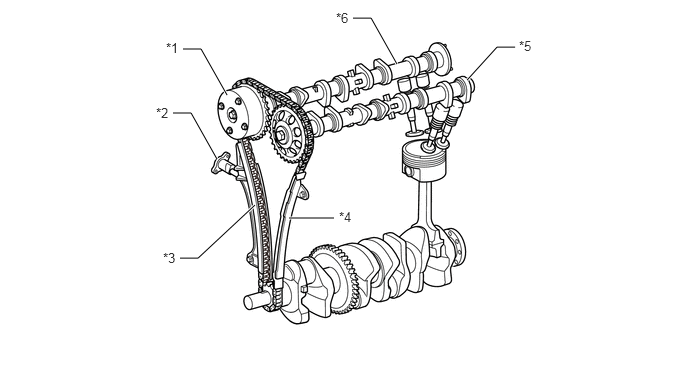
W135168C01
3.01,2.271 3.479,2.271 true 1.906,0.51 2.094,0.51 2.094,0.51 2.365,0.99 true 1.802,1.177 1.99,1.177 1.99,1.177 2.26,1.656 true 1.875,2.688 2.063,2.688 2.063,2.688 2.656,2.135 true 4.865,0.833 5.177,0.49 5.177,0.49 5.365,0.49 true 3.677,0.188 3.865,0.188 3.865,0.188 4.135,0.667 true 1.729,0.417 2.042,0.573 0.313,0.156 10 false *1 1.625,1.094 1.958,1.323 0.333,0.229 10 false *2 1.698,2.604 2.01,2.76 0.313,0.156 10 false *3 3.531,2.177 3.844,2.396 0.313,0.219 10 false *4 5.406,0.396 5.719,0.552 0.313,0.156 10 false *5 3.5,0.104 3.813,0.26 0.313,0.156 10 false *6
*1 VVT-i Controller *2 Chain Tensioner
*3 Chain Slipper *4 Chain Damper
*5 Exhaust Camshaft *6 Intake Camshaft


W135182C01
3.927,1.552 4.396,1.552 true 3.74,0.656 3.99,0.281 3.99,0.281 4.146,0.281 true 4.208,0.188 4.521,0.344 0.313,0.156 10 false *1 4.427,1.469 4.74,1.625 0.313,0.156 10 false *2
*1 Camshaft *2 Valve Lifter


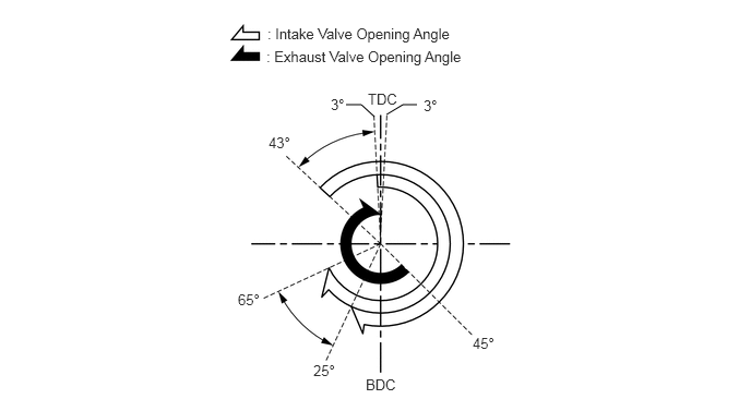
Valve Timing
W135226E01
3.302,1 3.448,1 3.448,1 3.573,1.115 false 3.688,1.094 3.844,1 3.844,1 3.979,1 false 2.552,0.24 4.448,0.625 1.896,0.385 10 false : Intake Valve Opening Angle 2.542,0.458 4.438,0.844 1.896,0.385 10 false : Exhaust Valve Opening Angle 3.51,0.865 3.896,1.177 0.385,0.313 10 false TDC 3.156,0.917 3.479,1.219 0.323,0.302 10 false 3° 4.042,0.927 4.365,1.229 0.323,0.302 10 false 3° 2.563,1.281 2.948,1.604 0.385,0.323 10 false 43° 2.271,2.781 2.656,3.104 0.385,0.323 10 false 65° 2.99,3.458 3.375,3.781 0.385,0.323 10 false 25° 3.49,3.594 4.094,3.792 0.604,0.198 10 false BDC 4.51,3.198 4.896,3.521 0.385,0.323 10 false 45°

HINT:

The adjustment of the valve clearance is accomplished by selecting and replacing the appropriate valve lifters.

A total of 35 valve lifters are available in 0.02 mm (0.008 in.) increments, from 5.06 mm (0.199 in.) to 5.74 mm (0.226 in.). For details, refer to the Repair Manual.


j.

Camshaft

i.

The intake camshaft is provided with the timing rotor to trigger the camshaft position sensor.


ii.

In conjunction with the adoption of the VVT-i system, an oil passage is provided in the intake camshaft in order to supply engine oil pressure to the VVT-i system.


iii.

A VVT-i controller has been installed on the front of the intake camshaft to vary the timing of the intake valves.
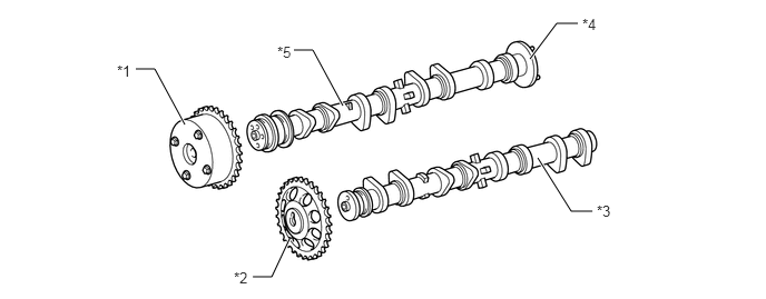
W135169C01
1.271,0.646 1.448,0.646 1.448,0.646 1.729,1.167 true 2.75,0.469 2.927,0.469 2.927,0.469 3.208,0.99 true 2.365,2.594 2.542,2.594 2.542,2.594 2.708,2.24 true 5.031,1.479 5.344,1.979 5.344,1.979 5.542,1.979 true 4.958,0.552 5.208,0.219 5.208,0.219 5.406,0.219 true 1.094,0.583 1.417,0.802 0.323,0.219 10 false *1 2.188,2.521 2.5,2.677 0.313,0.156 10 false *2 5.583,1.896 5.938,2.094 0.354,0.198 10 false *3 5.448,0.146 5.76,0.302 0.313,0.156 10 false *4 2.594,0.406 2.906,0.563 0.313,0.156 10 false *5
*1 VVT-i Controller *2 Timing Sprocket
*3 Exhaust Camshaft *4 Timing Rotor
*5 Intake Camshaft - -


k.

Timing Chain

i.

A roller chain with an 8 mm (0.315 in.) pitch is used to make the engine more compact.


ii.

The timing chain is lubricated by an oil jet.


iii.

The chain tensioner uses a spring and oil pressure to maintain proper chain tension at all times.


iv.

The chain tensioner suppresses noise generated by the timing chain.


v.

A ratchet type non-return mechanism is used.


vi.

To achieve excellent serviceability, the chain tensioner is constructed so that it can be removed and installed from the outside of the timing chain cover.
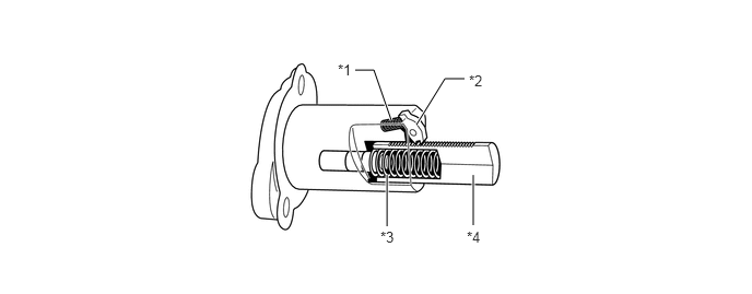
Chain Tensioner
W135170C01
4.51,2.146 4.51,1.667 true 3.688,2.156 3.688,1.667 true 3.969,1.188 4.24,0.75 4.24,0.75 4.427,0.75 true 3.385,0.667 3.563,0.667 3.563,0.667 3.729,1.146 true 3.219,0.583 3.531,0.74 0.313,0.156 10 false *1 4.469,0.688 4.781,0.844 0.313,0.156 10 false *2 3.625,2.177 3.979,2.417 0.354,0.24 10 false *3 4.448,2.177 4.813,2.469 0.365,0.292 10 false *4
*1 Cam Spring *2 Cam
*3 Spring *4 Plunger


W135171C01
2.208,1.958 3.354,1.958 true 2.229,0.792 2.417,0.792 2.417,0.792 2.792,1.271 true 3.531,2.375 4.677,2.375 true 3.75,1.281 4.656,1.281 true 3.865,0.917 4.646,0.917 true 2.052,0.719 2.365,0.875 0.313,0.156 10 false *1 2.042,1.875 2.354,2.031 0.313,0.156 10 false *2 4.729,2.281 5.042,2.438 0.313,0.156 10 false *3 4.698,1.188 5.021,1.396 0.323,0.208 10 false *4 4.698,0.823 5.01,0.979 0.313,0.156 10 false *5
*1 Chain Tensioner *2 Chain Slipper
*3 Oil Jet *4 Chain Damper
*5 Timing Chain - -


l.

Serpentine Belt Drive System

i.

Accessory components are driven by a serpentine belt consisting of a single V-ribbed belt. It reduces the overall engine length, weight and the number of engine parts.


ii.

An automatic tensioner eliminates the need for tension adjustment.
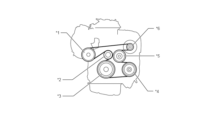
W135183C01
4.156,1.885 5.198,1.885 true 2.042,1.104 2.24,1.104 2.24,1.104 2.844,1.771 true 2.104,2.688 2.438,2.688 2.438,2.688 3.531,1.885 true 2.104,3.24 2.469,3.24 2.469,3.24 3.417,2.5 true 4.49,2.427 4.969,3.073 4.969,3.073 5.156,3.073 true 4.448,1.542 4.99,0.958 4.99,0.958 5.177,0.958 true 1.875,1.021 2.188,1.177 0.313,0.156 10 false *1 1.927,2.604 2.24,2.76 0.313,0.156 10 false *2 1.927,3.156 2.24,3.313 0.313,0.156 10 false *3 5.219,3 5.604,3.229 0.385,0.229 10 false *4 5.25,1.802 5.563,1.958 0.313,0.156 10 false *5 5.25,0.875 5.563,1.031 0.313,0.156 10 false *6
*1 Idler Pulley *2 Idler Pulley for Automatic Tensioner
*3 Crankshaft Pulley *4 Air Conditioner Compressor Pulley
*5 Water Pump Pulley *6 Alternator Pulley


m.

Automatic Tensioner

i.

The automatic tensioner consists of an idler pulley and a tensioner. The idler pulley maintains belt tension by the force of the spring that is located in the tensioner.
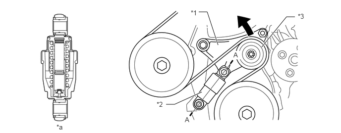
W135185C01
4.177,0.25 4.354,0.25 4.354,0.25 4.583,0.948 true 3.49,2.198 3.667,2.198 3.667,2.198 4.24,1.938 true 5.5,0.99 6.021,0.354 6.021,0.354 6.198,0.354 true 4.01,0.188 4.323,0.344 0.313,0.156 10 false *1 3.292,2.115 3.604,2.271 0.313,0.156 10 false *2 6.26,0.26 6.594,0.479 0.333,0.219 10 false *3 1.188,2.594 1.5,2.75 0.313,0.156 10 false *a 3.885,2.438 4.198,2.594 0.313,0.156 10 false A 4.906,1.073 5.063,1.25 0.156,0.177 10 true A
*1 Arm *2 Tensioner
*3 Idler Pulley - -
*a A-A Cross Section - -


n.

VVT-i Controller

i.

The VVT-i controller consists of the housing driven by the timing chain and the vane fixed on the intake camshaft.


ii.

The oil pressure sent from the advance or retard side path at the intake camshaft causes rotation in the VVT-i controller vane circumferential direction to vary the intake valve timing continuously.


iii.

When the engine is stopped, the intake camshaft will be in the most retarded state to ensure startability.


iv.

When hydraulic pressure is not applied to the VVT-i controller immediately after the engine has been started, the lock pin locks the movement of the VVT-i controller to prevent a knocking noise.
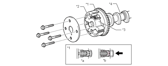
W135167C01
2.802,1.896 5.604,2.729 2.802,0.833 3.823,0.177 3.979,0.177 3.979,0.177 4.177,0.656 true 3.417,0.281 3.573,0.281 3.573,0.281 3.708,0.563 true 4.208,0.906 4.948,1.271 4.948,1.271 5.177,1.271 true 4.813,0.156 4.969,0.156 4.969,0.156 5.167,0.635 true 3.656,0.094 3.969,0.25 0.313,0.156 10 false *1 3.25,0.188 3.563,0.344 0.313,0.156 10 false *2 5.219,1.177 5.531,1.333 0.313,0.156 10 false *3 4.656,0.083 4.969,0.24 0.313,0.156 10 false *4 3.458,2.49 3.771,2.646 0.313,0.156 10 false *a 4.396,2.479 4.708,2.635 0.313,0.156 10 false *b 2.865,1.948 3.177,2.104 0.313,0.156 10 false *1
*1 Lock Pin *2 Housing
*3 Vane (Fixed on Intake Camshaft) *4 Intake Camshaft
*a At a Stop *b In Operation
V100135

Oil Pressure - -


o.

Camshaft Timing Oil Control Valve

i.

The camshaft timing oil control valve controls the spool valve position in accordance with the duty cycle control from the engine ECU thus allocating the hydraulic pressure that is applied to the VVT-i controller to the advance and the retard side. When the engine is stopped, the camshaft timing oil control valve is in the most retarded state.
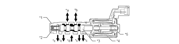
W135165C01
1.729,0.708 1.865,0.708 1.865,0.708 2.083,0.979 true 1.729,1.531 1.865,1.531 1.865,1.531 2.115,1.208 true 3.313,1.177 3.698,1.667 3.698,1.667 3.833,1.667 true 4.26,1.438 4.49,1.667 4.49,1.667 4.625,1.667 true 4.583,1.167 4.813,1.396 4.813,1.396 4.948,1.396 true 1.573,0.635 1.885,0.792 0.313,0.156 10 false *1 1.573,1.448 1.885,1.604 0.313,0.156 10 false *2 3.875,1.583 4.188,1.74 0.313,0.156 10 false *3 4.667,1.583 4.979,1.74 0.313,0.156 10 false *4 5,1.313 5.313,1.51 0.313,0.198 10 false *5 2.625,0.333 2.938,0.49 0.313,0.156 10 false *a 2.979,0.323 3.292,0.479 0.313,0.156 10 false *b 2.104,1.573 2.417,1.729 0.313,0.156 10 false *c 2.688,1.573 3,1.729 0.313,0.156 10 false *d 2.365,1.573 2.677,1.729 0.313,0.156 10 false *c 3,1.563 3.313,1.719 0.313,0.156 10 false *c 3.385,1.563 3.698,1.719 0.313,0.156 10 false *c
*1 Sleeve *2 Spring
*3 Spool Valve *4 Coil
*5 Plunger - -
*a To VVT-i Controller (Advance Side) *b To VVT-i Controller (Retard Side)
*c Drain *d Oil Pressure