2AZ-FE BATTERY / CHARGING CHARGING SYSTEM GENERAL/CONTROL/DETAILS DETAILS
SYSTEM CONTROL
Dual Winding System
This type alternator uses a dual winding system. This system consists of two sets of three-phase windings whose phases are staggered 30°. Because the magnetic fluctuations of the respective windings cancel each other out, magnetic noise and radio frequency interference are reduced.
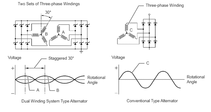
Charging Control
The charging system lowers the generated voltage except when the vehicle is decelerating, and raises the generated voltage when the vehicle is decelerating. This reduces the load on the engine as a result of the electric generation of the generator, thus contributing to the fuel economy of the engine.
This control consists of the ECM, battery current sensor assembly with a built-in battery temperature sensor, generator and various sensors and switches.
The ECM stops charging control and the generator switches to normal power generation mode under the following conditions:
Engine started
Wipers operating or blower motor operating with taillight relay on
Low or high battery temperature
Battery current sensor assembly with a built-in battery temperature sensor malfunctions
Sensor malfunctions (speed sensors, throttle position sensor, crank position sensor, or acceleration sensor)
Low battery
CONSTRUCTION
Alternator Pulley
A helical coil type one-way clutch is used on the alternator pulley in order to reduce the load that acts on the auxiliary equipment belt.
The pulley mounting nut and the alternator pulley have been integrated to achieve a compact construction.
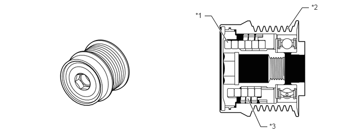
| *1 | Coil Spring | *2 | Pulley |
| *3 | Helical Coil Type One-way Clutch | - | - |
Battery Current Sensor Assembly
Installed on the negative terminal of the battery, this sensor detects the amount of charging and discharging amperage of the battery and sends signal to the ECM. Based on this signal, the ECM calculates the battery capacity.
A Hall IC is used for detecting the amount of charging and discharging amperage. The changes that occur in the magnetic flux density in the core as a result of the charging and amperage of the battery are converted and output as voltage.
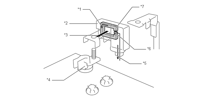
| *1 | Magnetic Field | *2 | Battery Current Sensor Assembly |
| *3 | Charge/discharge Current | *4 | Negative Terminal of the Battery |
| *5 | Charge/discharge Amount Signal | *6 | Hall IC |
| *7 | Core | - | - |
Battery Temperature Sensor
The battery temperature sensor is built into the battery current sensor assembly.
The battery characteristic (battery internal resistance) of taking in current for charging varies according to battery electrolyte temperature. If the electrolyte temperature is too low or too high, the battery internal resistance will increase, resulting in early deterioration. To prevent this, the battery temperature sensor changes resistance to detect the temperature.
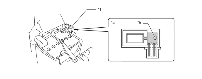
| *1 | Battery Current Sensor Assembly | - | - |
| *a | Battery Current Sensor Assembly Cross Section | *b | Sensor Portion |