THEFT DETERRENT / KEYLESS ENTRY SMART ENTRY AND START SYSTEM GENERAL/CONTROL/DETAILS DETAILS
FUNCTION OF MAIN COMPONENTS
| Component | Function |
|---|---|
| Engine Switch
·
Transponder Key Amplifier |
·
Transmits the engine switch signal to the main body ECU. ·
Informs the driver of a power source mode or system abnormality with the illumination state of the indicator light. ·
Receives the ID code and transmits it to the certification ECU when the key battery is low. |
| Key | Receives the signals from oscillators and returns the ID code to the tuner. |
| Room Oscillator
·
Front, Rear and Luggage |
Receives a request signal from the certification ECU and forms the actuation area in the vehicle interior. |
| Tuner | Receives the ID code from the key and transmits it to the certification ECU. |
| Main Body ECU | ·
Switches the power source modes in four modes (OFF, ACC, IG-ON, START) in accordance with the shift position and the state of the stop light switch, or the state of the clutch start switch. ·
Controls the start function in accordance with the signals received from the switches and each ECU. |
| Certification ECU | Certificates the ID code received from the tuner and transmits the certification results to the ID code box and steering lock ECU. |
| Stop Light Switch | Outputs the state of the brake pedal to the main body ECU. |
| ID Code Box | Receives the steering unlock or engine immobilizer unset request signal from the certification ECU, certifies them, and transmits each unset signal to the steering lock ECU or engine ECU. |
| Engine ECU | ·
Receives the engine start request signal from the main body ECU, turns ON the ST relay, and starts the engine. ·
Receives the signal from the ID code box and performs engine ignition and injection. |
| Component | Function | |
|---|---|---|
|
*: Except China Models |
||
| Key | ·
When receiving the request signals that are output by the room and door oscillators, outputs the information such as the key ID and vehicle ID. ·
When a driver pushes the LOCK or UNLOCK button on the key, outputs the request signal. ·
When receiving the radio wave that is output by the transponder key amplifier in the engine switch, outputs the information such as the key ID and vehicle ID. ·
Integrates the mechanical key in order to unlock the doors when the key battery is low. |
|
| Certification ECU | ·
Judges and certifies the key (valid or invalid). ·
Controls the room and door oscillators, and the touch sensor. ·
Transmits the door lock/unlock request signals during the entry function. ·
Transmits the steering lock/unlock request signals. ·
Transmits the engine immobilizer set/unset request signals. ·
Records the ID codes between the certification ECU, ID code box, and steering lock ECU. |
|
| Main Body ECU | Controls the push button start system in accordance with the signals from the various switches, ECUs and combination meter.
·
Transmits the key certification request signal to the certification ECU in accordance with the engine switch signal, and turns the relays ON and OFF. ·
Receives the request signal from the certification ECU and actuates the door lock motor to unlock or lock all the doors and back door. ·
Transmits each door condition to the certification ECU. |
|
| ID Code Box | Receives the steering unlock or engine immobilizer unset request signals from the certification ECU, certifies them, and transmits each signal to the steering lock ECU or engine ECU. | |
| Outside Door Handle | Antenna | Transmits the request signals. |
| Touch Sensor | Transmits the door unlock request signal to the certification ECU. | |
| Lock Switch | Transmits the door lock or all door window close request signal to the certification ECU. | |
| Door Oscillator
·
Front RH and LH |
Receives the request signal from the certification ECU, and forms the actuation area around each door. | |
| Room Oscillator
·
Front, Rear and Luggage |
Receives the request signal from the certification ECU, and forms the actuation area in the vehicle interior. | |
| Back Door Outer Oscillator | Only when the back door open/lock switch is pressed, receives the request signal from the certification ECU, and forms the actuation area around the back door. | |
| Tuner | Receives the ID code from the key in the actuation area and transmits it to the certification ECU. | |
| Back Door Open Switch | Transmits a back door open request signal to the main body ECU. | |
| Back Door Lock Switch | Transmits a back door lock request signal to the certification ECU. | |
| Stop Light Switch | Outputs the state of the brake pedal to the main body ECU. | |
| Wireless Door Lock Buzzer | Sounds as an answerback for entry lock or unlock to inform the driver.* | |
| Combination Meter | Smart Entry & Start System Warning Light | When the certification ECU detects human errors, it warns the driver by sounding the wireless door lock buzzer, illuminating the smart entry & start system warning light and sounding the buzzer in the combination meter in accordance with the request signal from the ECU. |
| Buzzer | ||
FUNCTION
START FUNCTION
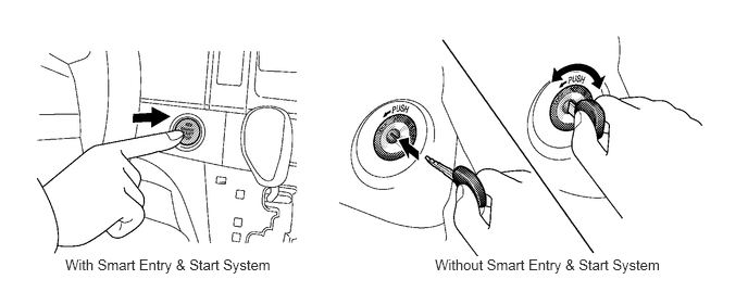
On the models without the smart entry & start system, the ignition key is inserted into the key cylinder and turned to switch the ignition switch position from the OFF position to the ACC, IG-ON or START position.
On the models with the smart entry & start system, it is operated simply by pressing the push-type engine switch while carrying the key. The main body ECU turns OFF and ON the ACC, IG1, IG2 or ST CUT relays to switch the power source mode.
This function has different power source mode patterns to suit the brake pedal condition and shift lever position, or clutch pedal condition.
Along with the adoption of the start function, an engine cranking hold function is used.
SYSTEM CONTROL
ACTUATION AREA
The functions of the smart entry & start system only work when the key is in the actuation area formed by the six oscillators.
The front, rear and luggage room oscillators form the actuation area of the start function.
Two door oscillators form the actuation area of the entry function.
The back door outer oscillator forms the actuation area of the entry back door open function.
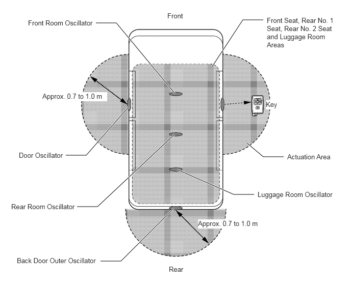
The front room oscillator forms the actuation area in the upper sections of the driver seat and front passenger seat.
The rear room oscillator forms the actuation area in the upper section of the rear No. 1 seat.
The luggage room oscillator forms the actuation area in the upper section of the rear No. 2 seat and in the luggage room.
CONSTRUCTION
Engine Switch
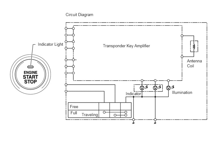
The engine switch consists of the momentary type switch, two color (amber, green) LEDs, and transponder key amplifier.
The amber and green LEDs are for the indicator light.
The driver can check the present power source mode and whether the engine can start or not in accordance with the illumination state of the indicator light.
When the main body ECU detects an abnormality in the start system while the engine is running, it makes the amber indicator light flash. If the engine stopped in this state, it might not be possible to restart it.
| Power Source Mode/Condition | Indicator Light Condition | |
|---|---|---|
| Brake pedal not depressed | Brake pedal depressed with shift lever in "P" or "N" | |
| OFF | Turn OFF | Turn ON (Green) |
| ACC, IG-ON | Turn ON (Amber) | Turn ON (Green) |
| Engine Running | Turn OFF | Turn OFF |
| Steering Lock not Unlocked | Flash (Green) for 15 seconds | Flash (Green) for 15 seconds |
| Start System Malfunction | Flash (Amber) for 15 seconds | Flash (Amber) for 15 seconds |
Main Body ECU
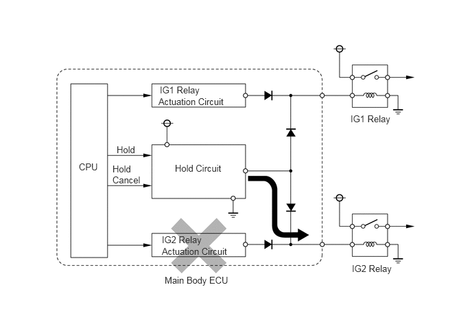
The main body ECU consists of the IG1 and IG2 relay actuation circuits, CPU, and hold circuit.
The hold circuit is installed to prevent the power supply to the relays from being cut off when an abnormality occurs in IG1 and/or IG2 relay actuation circuits during driving.
- HINT:
-
Service Tip:
-
The main body ECU constantly stores the present power source mode in its memory. Therefore, if the power to the main body ECU is interrupted due to the removal of the battery, the main body ECU restores the power source mode after the battery is reconnected.
-
For this reason, if the battery is removed when the power source mode is in the mode other than OFF, the power source mode will be restored to the vehicle at the same time the power source mode is restored to the main body ECU (by reconnecting the battery).
-
Therefore, before removing or disconnecting the battery, make sure to select the power source mode to OFF.
Key
The key consists of a mechanical key, transmitter for the wireless door lock remote control and transceiver for the smart entry & start system.
The transceiver for the smart entry & start system receives the signals from the oscillators and returns the ID code to the tuner.
The transmitter for the wireless door lock remote control has a LOCK button and UNLOCK button.
When the key battery is low, the key returns to the engine switch the radio wave response received from the engine switch.
This mechanical key works for the driver door, back door storage extension and glove box, but cannot start the engine.
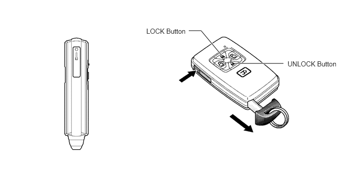
Oscillator (Front LH & RH Doors, Front, Rear and Luggage Rooms and Back Door)
Each oscillator transmits the request signal received from the certification ECU, and forms a key actuation area to detect the presence of a key.
The actuation area formed by front LH & RH door oscillators and back door outer oscillator are approximately 0.7 to 1.0 m (27.6 to 39.4 in.) from the outside door handle of the front LH & RH doors, or the center of the rear bumper.
The actuation area of the front LH & RH door oscillators are formed by transmitting a request signal every 250 ms while the power source mode is OFF and each door is locked. In this way it detects the proximity of a key. During entry lock, the actuation area is formed with the lock switch ON.
The actuation area of the front, rear and luggage room oscillators are formed when the driver door is opened or closed, during start ignition, when a warning is activated, or when the lock switch is ON.
The actuation area of the back door outer oscillator is formed when the back door open switch is ON.
OPERATION
Start Function Operation
The start function has different power source mode patterns to suit the brake pedal condition and shift lever position.
| Pattern | Brake Pedal | Shift Lever | Power Source Mode Pattern |
|---|---|---|---|
| A | Depressed | P or N Position | When the engine switch is pushed once.
·
OFF → IG-ON (After the engine is started) |
| B | Not Depressed | P Position | Each time the engine switch is pushed.
·
OFF → ACC → IG-ON → OFF |
| C | Except P Position | Each time the engine switch is pushed.
·
OFF → ACC → IG-ON → ACC |
|
| D | - | P Position | When the engine switch is pushed in the IG-ON mode.
·
IG-ON (Engine is started or not started) → OFF |
| E | - | Except P Position | When the engine switch is pushed in the IG-ON mode.
·
IG-ON (Engine is started or not started) → ACC |
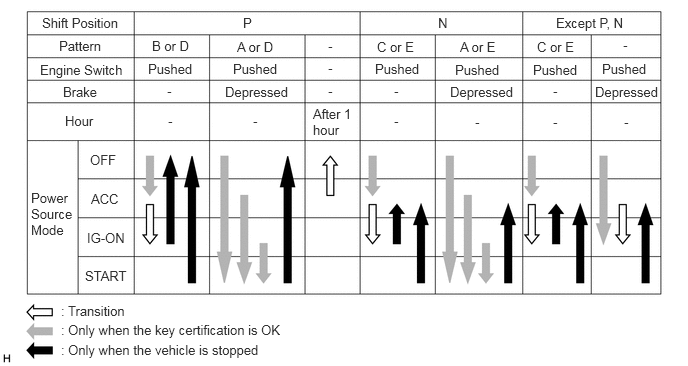
- HINT:
- ·
Normally, the operation of the engine switch is disabled while the vehicle is being driven.However, if the engine must be stopped in an emergency while the vehicle is in motion, the driver can press the engine switch for approximately 3 seconds or more to stop the engine.
·If no signals are transmitted to the main body ECU due to malfunctions in the stop light switch system, the engine may not start when the engine switch is pressed with the brake pedal depressed. In such cases, performing the following procedures may be enable the engine to start: 1) press the engine switch to turn the power source mode from OFF to ACC, and 2) press the engine switch again and hold it for 15 seconds or more.
·Above two operations must be applied only in emergency situations. Under normal conditions, the engine must not be stopped by pressing the engine switch during driving or started without depressing the brake pedal when the shift lever is in any position other than P or N.
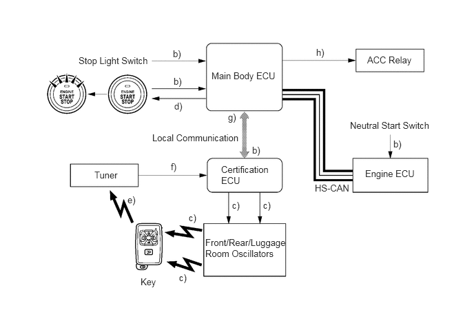
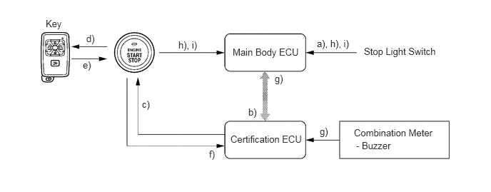
Pattern A: OFF → IG-ON (After the engine is started)
| Step | System Operation |
|---|---|
| a) | The driver enters the vehicle with the key carried in the driver's possessions. |
| b) | When the driver presses the engine switch once with the following conditions satisfied, the main body ECU recognizes the engine switch signal and transmits the key certification request signal to the certification ECU.
·
Shift position is "P" or "N". ·
Brake pedal is depressed. ·
Power source mode is in "OFF". |
| c) | The certification ECU receives the key certification request signal and transmits a request signal to the front/rear/luggage room oscillators. These oscillators then transmit the request signal. |
| d) | The main body ECU turns ON the green indicator light of the engine switch. |
| e) | At the moment the key receives the request signal, it returns to the tuner an ID code that includes the response code. |
| f) | The tuner receives this code and transmits it to the certification ECU. |
| g) | The certification ECU judges and certifies the ID code, and transmits a key certification OK signal to the main body ECU. |
| h) | After receiving the key certification OK signal, the main body ECU turns ON the ACC relay. |
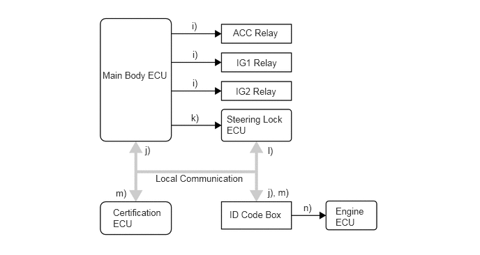
| Step | System Operation |
|---|---|
| i) | The main body ECU turns ON the ACC relay, and then turns ON the IG1 and IG2 relays. |
| j) | The certification ECU checks that the power source mode has switched from OFF to IG-ON, and transmits a steering unlock request signal to the main body ECU and ID code box. |
| k) | The main body ECU receives this signal and supplies power to the steering lock ECU. |
| l) | The steering lock ECU receives the steering unlock request signal via the ID code box, and releases the steering lock. |
| m) | After checking the steering unlock condition, the certification ECU transmits an engine immobilizer unset request signal to the ID code box. |
| n) | The ID code box certifies the engine immobilizer unset signal of the certification ECU, transmits the engine immobilizer unset request signal to the engine ECU, and unsets the engine immobilizer. |
| Step | System Operation |
|---|---|
| o) | After checking the steering is in the unlock condition, the main body ECU transmits a starter request (STSW) signal to the engine ECU. |
| p) | The engine ECU outputs an ST relay (START) signal, and actuates the starter. |
| q) | If the ST relay (START) signal cannot be output because the power supplied to the engine ECU is low, the main body ECU outputs the ST relay (START) signal instead to help actuate the starter. |
| r) | When the engine ECU judges from the engine speed signal that engine start is completed, it stops the ST relay (START) signal, and stops the starter. |
| s) | The main body ECU checks that engine start is completed, and turns OFF the indicator light of the engine switch. |
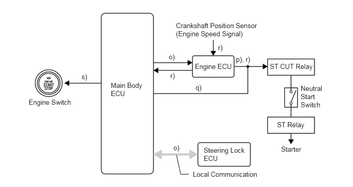
Pattern B: OFF → ACC → IG-ON → OFF
OFF → ACC
| Step | System Operation |
|---|---|
| a) | The driver enters the vehicle with the key carried in the driver's possessions. |
| b) | When the driver presses the engine switch once with the following conditions satisfied, the main body ECU recognizes the engine switch signal and transmits the key certification request signal to the certification ECU.
·
Shift position is "P". ·
Brake pedal is not depressed. ·
Power source mode is in "OFF". |
| c) | When the brake pedal is not depressed, the main body ECU turns ON the amber indicator light of the engine switch. |
| d) | The subsequent system operation is the same as d) to h) in pattern "A". |
ACC → IG-ON
| Step | System Operation |
|---|---|
| a) | When the power source mode is "ACC" and the driver presses the engine switch again, the main body ECU recognizes the engine switch signal and turns ON the IG1 and IG2 relays. |
| b) | The subsequent system operation is the same as j) to n) in pattern "A". |
IG-ON → OFF
| Step | System Operation |
|---|---|
| a) | When the engine switch is pressed once with the following conditions satisfied, the main body ECU recognizes the engine switch signal and turns OFF the ACC, IG1 and IG2 relays.
·
Shift position is "P". ·
Brake pedal is not depressed. ·
Vehicle speed is 0. ·
Power source mode is in "IG-ON". |
| b) | When the power source mode is switched from IG-ON to OFF, the main body ECU turns OFF the indicator light of the engine switch. |
| c) | If the driver door is opened, the main body ECU receives a signal from the courtesy switch (for driver door). Then, power supply to the steering lock ECU stops to lock the steering. |
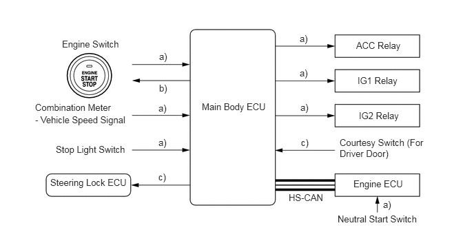
Pattern C: OFF → ACC → IG-ON → ACC
| Step | System Operation |
|---|---|
| a) | The system operations for the power source mode "OFF → ACC → IG-ON" are the same as those in pattern B. |
| b) | When the engine switch is pressed once with the following conditions satisfied, the main body ECU recognizes the engine switch signal and turns OFF the IG1 and IG2 relays.
·
Shift position is except "P". ·
Brake pedal is not depressed. ·
Vehicle speed is 0. ·
Power source mode is in "IG-ON". |
| c) | Even after the power source mode switches from IG-ON to ACC, the indicator light of the engine switch remains illuminated in amber. |
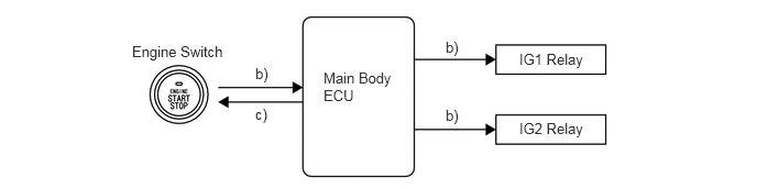
Pattern D: IG-ON → OFF
This system operation is the same as IG-ON → OFF for pattern "B".
Pattern E: IG-ON → ACC
This system operation is the same as pattern "C". For details, see above. However, the indicator light of the engine switch illuminates as follows:
When the power source mode is switched from IG-ON to ACC, the main body ECU makes the amber indicator light of the engine switch continue to illuminate.
When the power source mode is switched from engine running to OFF, the main body ECU turns OFF the indicator light of the engine switch.
When Key Battery is Low
| Step | System Operation |
|---|---|
| a) | To operate the start system when the key battery is low, hold the TOYOTA mark of the key against the engine switch while depressing the brake pedal. |
| b) | The main body ECU transmits a key certification request signal to the certification ECU. |
| c) | The certification ECU does not receive an ID code response from the tuner, so it actuates the transponder key amplifier built into the engine switch. |
| d) | The transponder key amplifier outputs an engine immobilizer radio wave to the key. |
| e) | The key receives the radio wave, and returns a radio wave response to the transponder key amplifier. |
| f) | The transponder key amplifier combines the key ID codes with the radio wave response, and transmits it to the certification ECU. |
| g) | The certification ECU judges and verifies the ID code, and transmits a key certification OK signal to the main body ECU. The buzzer in the combination meter sounds at the same time. |
| h) | After the buzzer sounds, if the engine switch is pressed within five seconds while the brake pedal is depressed, the power source mode switches to START as in the normal condition. |
| i) | After the buzzer sounds, if the engine switch is pressed within five seconds while the brake pedal is not depressed, the power source mode switches to ACC or IG-ON as in the normal condition. |
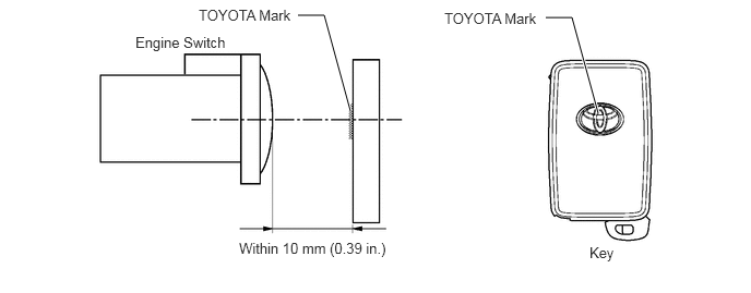
Entry Function Operation
The entry function has the following functions.
| Function | Outline |
|---|---|
| Wireless Door Lock Remote Control | This function is a convenient system for locking and unlocking all the doors and back door at a distance. The operation of this function in the smart entry & start system is the same as that in the wireless door lock remote control system. However, the receiver in the certification ECU uses a tuner to perform the control. |
| Entry Illumination | When a key enters any actuation area of the door oscillator, the foot light, front personal light, room light and engine switch illumination illuminate. |
| Entry Unlock | When a key is located in any actuation area of the door oscillator, the door will be unlocked with the touch of an outside door handle. |
| Entry Lock | When a key is located in any actuation area of the door oscillator and the power source mode is OFF, the door will be locked by merely pressing the lock switch on the outside door handle. |
| Entry Back Door Open | When a key is in an actuation area of the back door outer oscillator, the back door opens by merely pressing the back door open switch. |
| Prevention of Key Confinement | Prevents the confinement of the key if all the doors and back door are locked from the outside door handle while the key is still inside the vehicle. |
| Warning | The smart entry & start system causes the certification ECU to sound the buzzer in the combination meter and the wireless door lock buzzer, and illuminate the smart entry & start system warning light in order to alert the driver. |
| Battery Saving | This function extends the signal transmission (between the system and key) interval from 250 ms to 750 ms, or automatically deactivates the smart entry & start system in order to prevent the vehicle and/or key battery from being drained. |
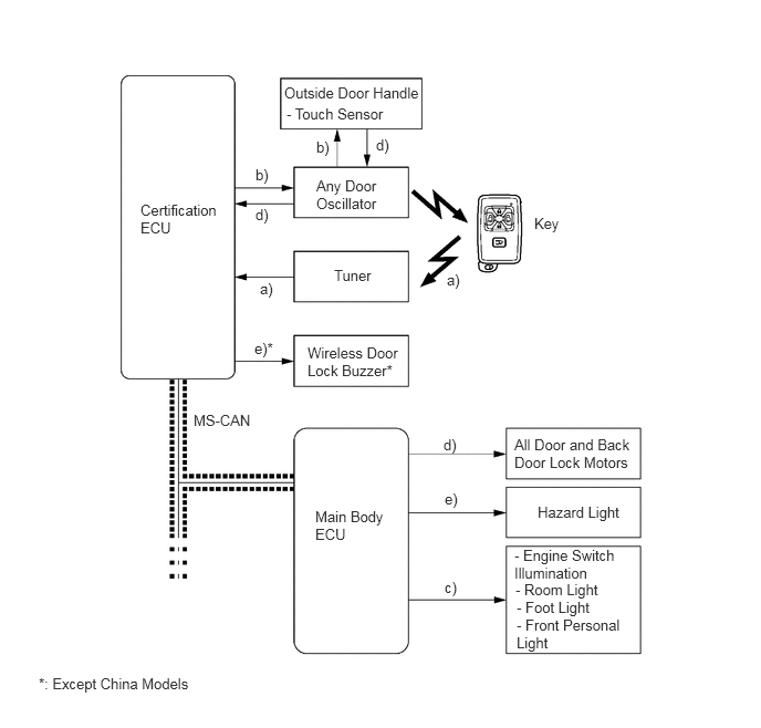
Entry Unlock
When a key enters any actuation area of the door oscillators, the certification ECU judges and certifies the ID code received from the tuner.
After the ID code is certified, the certification ECU transmits an unlock stand-by signal to the touch sensor of the relevant door.
At the same time, the certification ECU transmits a lighting signal for each illumination (foot light, front personal light, room light and engine switch illumination) via the main body ECU, and turns ON these illuminations. (Entry Illumination Function)
If the touch sensor is touched in this condition, the certification ECU transmits a door unlock request signal to the main body ECU, and unlocks all the doors and back door.
The certification ECU sounds twice the wireless door lock buzzer*, and the main body ECU flashes twice the hazard light, as an answerback for entry unlock.
Entry Lock
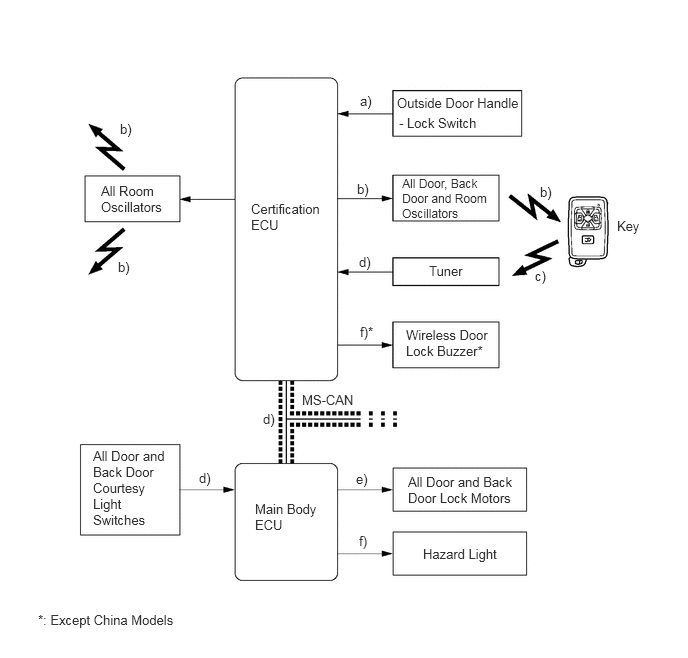
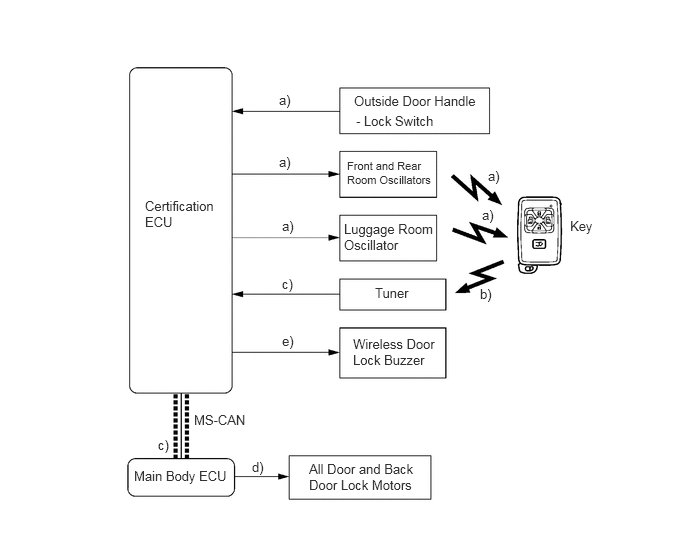
The lock signal is transmitted to the certification ECU when the driver exits the vehicle with the key carried in the driver's possessions and presses the lock switch.
The certification ECU transmits a request signal for all the doors, back door and room oscillators to form actuation areas.
The key transmits the ID code to the tuner.
The certification ECU judges and certifies the ID code from the tuner. It then checks the location of the key, and when all the doors and back door are closed, the ECU transmits a door lock request signal to the main body ECU.
The main body ECU actuates the door lock motors to lock all the doors and back door.
The certification ECU sounds once the wireless door lock buzzer*, and the main body ECU flashes once the hazard light, as an answerback for entry lock.
Entry Back Door Open
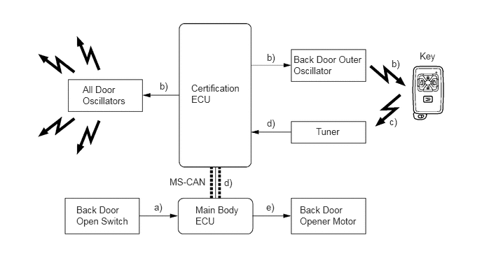
The unlock signal is transmitted to the certification ECU when the driver pushes the back door open switch with the key carried in the driver's possessions.
The certification ECU transmits a request signal for all the room and back door outer oscillators to form actuation areas.
The key transmits the ID code to the tuner.
The certification ECU judges and certifies the ID code, and checks the location of the key. The ECU transmits a back door open signal to the main body ECU.
The main body ECU receives this signal and actuates the back door opener motor to open the back door.
Prevention of Key Confinement
General
This function determines whether a key is confined in the interior room or the luggage compartment, unlocks the doors, and alerts the driver.
Inside Interior Room and Luggage Compartment
When the door is locked from the lock switch while the key is still inside the vehicle, the certification ECU transmits a request signal for the front, rear and luggage room oscillators to form a actuation area.
The key transmits the ID code to the tuner.
The certification ECU judges and certifies the ID code, and checks the location of the key. The ECU transmits a door unlock request signal to the main body ECU.
The main body ECU receives the signal and operates each door lock motor to unlock all the doors and back door.
The certification ECU sounds the wireless door lock buzzer for 2 seconds as a response to unlock.
Warning
General
When any of the situations below occur, the smart entry & start system causes the certification ECU to sound a buzzer in the combination meter and the wireless door lock buzzer, and illuminate the smart entry & start system warning light in order to alert the driver.
| Situation | Condition |
|---|---|
| A | The shift lever is in a position other than "P" and the power source mode is a mode other than "OFF". |
| B | The driver door is opened while the steering is unlocked. |
| C | The shift lever is in "P" and power source mode is a mode other than "OFF". |
| D | The entry lock is operated while any of the doors is open. |
| E | The occupant leaves with the key. |
| F | The engine switch is operated while the key is outside the actuation area. |
| G | The entry lock is operated while the key is inside the vehicle. |
| H | The key battery is low. |
| I | The steering lock cannot be released. |
| J | A steering lock ECU malfunction has been detected. |
| K | A main body ECU malfunction has been detected. |
| L | The system assumes that the driver is unfamiliar with the proper way to start the engine. |
Situation: A
There are two patterns for situation A.
Pattern 1. The door is opened and the user tries to leave the vehicle.
Pattern 2. In addition to the pattern 1, the user holds the key and tries to move away from the vehicle.
In these situations the following control is performed.
| Possible Effects without Warning | Sudden vehicle start, vehicle theft, vehicle roll-away | |
| Warning Condition | The certification ECU gives a warning when all the following conditions are satisfied.
·
Shift lever is except "P". ·
Power source mode is except "OFF". ·
Driver door is opened. ·
Vehicle speed is 0. |
|
| Warning Stop Condition | The warning is stopped when one of the following conditions is met.
·
Power source mode is "OFF". ·
Shift lever is "P". ·
Driver door is closed. ·
Vehicle speed is above 0. |
|
| Combination Meter | Buzzer | Continuous sound |
| Possible Effects without Warning | Sudden vehicle start, vehicle theft, vehicle roll-away | |
| Warning Condition | The certification ECU gives a warning when all the following conditions are satisfied.
·
Shift lever is except "P". ·
Power source mode is except "OFF". ·
The state of the driver door changed from open to close. ·
Vehicle speed is 0. ·
Key is not in the vehicle. |
|
| Warning Stop Condition | The warning is stopped when one of the following conditions is met.
Key is in the vehicle:
·
Combination meter buzzer and wireless door lock buzzer stop sounding. Vehicle speed is above 0:
·
Combination meter buzzer and wireless door lock buzzer stop sounding. Power source mode is except "IG-ON":
·
All warnings stop. |
|
| Combination Meter | Buzzer | Continuous sound |
| Smart Entry & Start System Warning Light | Turns ON | |
| Wireless Door Lock Buzzer | Continuous sound | |
Situation: B
In this situation the following control is performed.
| Possible Effects without Warning | Vehicle theft | |
| Warning Condition | The certification ECU gives a warning when one of the following conditions is met.
·
Power source mode is "ACC " or "OFF" and driver door is opened. ·
Power source mode is "OFF", steering is unlocked and driver door is opened. |
|
| Warning Stop Condition | The warning is stopped when one of the following conditions is met.
·
Power source mode is "IG-ON" or driver door is closed. ·
Power source mode is "OFF" and steering is locked. |
|
| Combination Meter | Buzzer | Intermittently sounds |
Situation: C
There are two patterns for situation C.
Pattern 1. When the shift lever is in "P", the door is closed and the user holds the key and tries to move away from the vehicle.
Pattern 2. In addition to the pattern 1, the user tries to use the entry lock and presses the lock switch.In these situations the following control is performed.
| Possible Effects without Warning | Vehicle theft, engine cannot be restarted | |
| Warning Condition | The certification ECU gives a warning when all the following conditions are satisfied.
·
Shift lever is "P". ·
Power source mode is except "OFF". ·
The state of the driver door changed from open to close. ·
Key is not in the vehicle. |
|
| Warning Stop Condition | The warning is stopped when one of the following conditions is met.
·
Power source mode is "OFF". ·
Key is in the vehicle. |
|
| Combination Meter | Buzzer | Sounds once |
| Smart Entry & Start System Warning Light | Turns ON | |
| Wireless Door Lock Buzzer | Sounds three times | |
| Possible Effects without Warning | Vehicle theft |
| Warning Condition | The certification ECU gives a warning when all the following conditions are satisfied.
·
Shift lever is "P". ·
Power source mode is except "OFF". ·
All doors are closed. ·
Key is not in the vehicle. ·
Lock switch is pushed. |
| Warning Stop Condition | The warning is stopped when one of the following conditions is met.
·
Power source mode is "OFF" and key is not in the vehicle. (Certification result for the outside of the vehicle is NG.) ·
Key is in the vehicle. (Certification result for the inside of the vehicle is OK and that for the outside of the vehicle is NG.) |
| Wireless Door Lock Buzzer | Sounds for 60 seconds |
Situation: D
In this situation the following control is performed.
| Possible Effects without Warning | Vehicle theft |
| Warning Condition | The certification ECU gives a warning when all the following conditions are satisfied.
·
Power source mode is "OFF". ·
Any door is opened. ·
The entry lock is operated. |
| Warning Stop Condition | The warning is stopped when one of the following conditions is met.
·
Power source mode is "IG-ON". ·
All doors are closed. ·
Wireless door lock remote function is unlocked. ·
The entry unlock is operated. ·
10 seconds have elapsed. |
| Wireless Door Lock Buzzer | Continuous sound |
Situation: E
In this situation the following control is performed.
| Possible Effects without Warning | Engine cannot be restarted | |
| Warning Condition | The certification ECU gives a warning when all the following conditions are satisfied.
·
Power source mode is in the mode other than "OFF". ·
The state of the any door other than the driver door changed from open to close. ·
Vehicle speed is 0. ·
Key is not in the vehicle. |
|
| Warning Stop Condition | The warning is stopped when one of the following conditions is met.
·
Power source mode is "OFF". ·
Vehicle speed is above 0. ·
Key is in the vehicle. |
|
| Combination Meter | Buzzer | Sounds once |
| Wireless Door Lock Buzzer | Sounds three times | |
Situation: F
In this situation the following control is performed.
| Possible Effects without Warning | Confuses the driver | |
| Warning Condition | The certification ECU gives a warning when all the following conditions are satisfied.
·
Engine switch is pushed. ·
Key is not in the vehicle. |
|
| Combination Meter | Buzzer | Sounds once |
| Smart Entry & Start System Warning Light | Turns ON for 8 seconds (Stops blinking after 8 seconds have elapsed.) | |
Situation: G
In this situation the following control is performed.
| Possible Effects without Warning | Vehicle theft |
| Warning Condition | The certification ECU gives a warning when all the following conditions are satisfied.
·
Power source mode is "OFF". ·
All doors are closed. ·
Lock switch is "ON". ·
Key is in the vehicle. |
| Wireless Door Lock Buzzer | Sounds for two seconds |
Situation: H
In this situation the following control is performed.
| Possible Effects without Warning | Smart entry & start system does not function | |
| Warning Condition | The certification ECU gives a warning when all the following conditions are satisfied.
·
Power source mode switches to "OFF" after being left in "IG-ON" for over 20 minutes. ·
Key battery voltage is low. ·
Key is in the vehicle. |
|
| Combination Meter | Buzzer | Sounds once |
Situation: I
In this situation the following control is performed.
| Possible Effects without Warning | Smart entry & start system does not function |
| Warning Condition | The steering lock is not released when the release operation is performed, preventing the engine from starting. |
| Engine Switch Indicator Light | Green color blinks in 1-second cycles (Stops blinking after 15 seconds have elapsed.) |
Situation: J
In this situation the following control is performed.
| Possible Effects without Warning | Engine cannot be started |
| Warning Condition | Internal malfunction in the steering lock ECU has been detected |
| Warning Stop Condition | Internal malfunction in the steering lock ECU has cleared |
| Engine Switch Indicator Light | Amber color blinks in 2-second cycles |
Situation: K
In this situation the following control is performed.
| Possible Effects without Warning | Engine cannot be started |
| Warning Condition | Internal malfunction in the main body ECU has been detected |
| Warning Stop Condition | Internal malfunction in the main body ECU has cleared |
| Engine Switch Indicator Light | Amber color blinks in 2-second cycles |
Situation: L
In this situation the following control is performed.
| Possible Effects without Warning | Smart entry & start system does not function |
| Warning Condition | The certification ECU gives a warning when all the following conditions are satisfied.
·
Power source mode is in the mode other than "IG-ON". ·
The state of the any door other than the driver door changed from open to close. ·
Power source mode is selected from "OFF" to "ACC" two or more times without starting the engine. |
| Warning Stop Condition | The warning is stopped when one of the following conditions is met.
·
10 seconds have elapsed after the warning. ·
Power source mode is "OFF". ·
Power source mode is "IG-ON". |
Battery Saving
Vehicle Battery Saving Function
In the smart entry & start system, signals are emitted outside of the vehicle at a prescribed interval (250 ms) when the doors are locked. Therefore, the vehicle battery could be drained if the vehicle remains parked for a long time. For this reason, the controls listed below are effected.
| Condition | Control |
|---|---|
| No response from key for more than 5 days | Signal transmission interval is extended from 250 ms to 750 ms. |
| No response from key for more than 14 days | Automatically deactivates the smart entry & start system. |
A wireless door lock remote control signal (lock, unlock, or back door open) is input and the key ID matches.
A driver carries the key and pushes the lock switch of the outside door handle.
A door is locked or unlocked by the mechanical key.
Key Battery and Vehicle Battery Saving Function
In the smart entry & start system, if the key is constantly located within the vehicle exterior actuation area of the door oscillators, the system maintains periodic communication with the key. Therefore, if the vehicle remains parked in that state for a long time, the key battery and the vehicle battery could be drained.
For this reason, if this state continues longer than 10 minutes, the smart entry & start system automatically becomes deactivated.
A wireless door lock remote control signal (lock, unlock, or back door open) is input and the key ID matches.
A driver carries the key and pushes the lock switch of the outside door handle.
A door is locked or unlocked by the mechanical key.
Leaving the key close to electrical appliances that emit radio waves could cause the key to accidentally respond, which could cause the key battery to become quickly depleted.
DIAGNOSIS
START FUNCTION
The main body ECU can detect malfunctions in the start function when the power source mode is IG-ON.When the ECU detects a malfunction, the amber indicator light of the engine switch flashes to warn the driver. At the same time, the ECU stores the 5-digit DTC (Diagnostic Trouble Code) in the memory.
The indicator light warning continues for 15 seconds even when the power source mode is switched to OFF.
The DTC can be read by connecting an intelligent tester II to the DLC3.
The start function cannot be operated again if a malfunction occurs.
- HINT:
-
For details, see the Previa/Tarago Repair Manual.