2GR-FE FUEL FUEL PUMP REASSEMBLY
PROCEDURE

 23280J
1.INSTALL FUEL PRESSURE REGULATOR ASSEMBLY
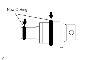
Apply a light coat of gasoline to 2 new O-rings, and install them onto the fuel pressure regulator.
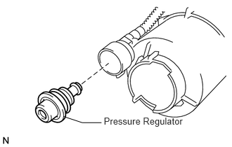
Install the fuel pressure regulator to the fuel filter.
23221
2.INSTALL FUEL PUMP ASSEMBLY
Connect the pump harness connector.
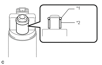
Apply gasoline to a new O-ring. Then install the O-ring and spacer to the fuel pump.
| *1 | O-ring |
| *2 | Fuel Pump Spacer |
Engage the 5 claws to install the fuel pump.
- NOTICE:
- ·
Make sure that the O-ring is not cut or pinched during the installation.
·Engage the claws securely.
3.INSTALL BRACKET
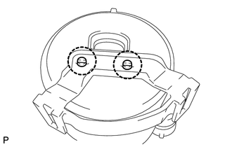
Engage the 2 claws and install the bracket.
4.INSTALL FUEL SUB-TANK ASSEMBLY
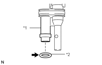
Apply gasoline to a new O-ring and install it to the jet pump.
| *1 | Jet Pump |
| *2 | O-ring |
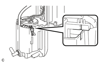
Install the jet pump while aligning it with the installation position of the sub-tank.
- NOTICE:
-
Make sure that the O-ring is not cut or pinched during the installation.
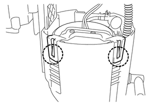
Attach the 2 claws to the claw holes and install the sub-tank.
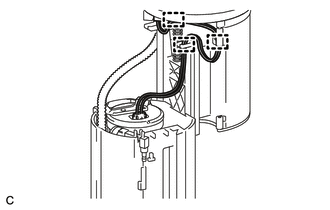
Install the wire harness.
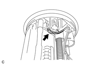
Connect the wire harness connector.
83320
5.INSTALL FUEL SENDER GAUGE ASSEMBLY
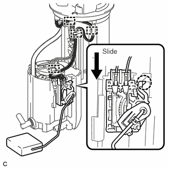
Install the fuel sender gauge assembly by sliding the sender gauge downward.
Connect the wire harness to the 4 harness clamps.
- NOTICE:
-
Do not damage the wire harness.
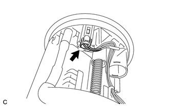
Connect the connector of the fuel sender gauge assembly.
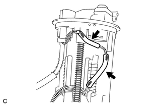
Install the 2 harness protectors.
- NOTICE:
-
Do not damage the wire harness.