2GR-FE EMISSION CONTROL AIR FUEL RATIO SENSOR ON-VEHICLE INSPECTION
CAUTION / NOTICE / HINT
- HINT:
-
The type of ignition switch on this model differs according to the specifications of the vehicle. For the expressions used in this section, refer to the "EXPRESSIONS OF IGNITION SWITCH" precaution (See page General>INTRODUCTION>REPAIR INSTRUCTION>PRECAUTION).
PROCEDURE

 89467B
1.CHECK AIR FUEL RATIO COMPENSATION SYSTEM
Connect the intelligent tester to the DLC3.
Turn the ignition switch on (IG).
Select the following menu items: Data List / A/FS B1 S1 and O2S B1 S2.
Warm up the A/F sensor with the engine speed at 2,500 rpm for approximately 2 minutes.
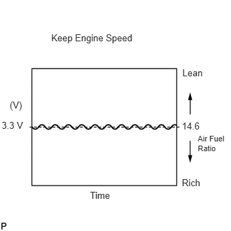
Keep the engine speed at 2,500 rpm and confirm that the "A/FS B1 S1" and "A/FS B2 S1" display is as shown in the illustration.
- HINT:
- ·
The illustration may slightly differ from the display on the intelligent tester.
·Only the intelligent tester displays the waveform of the A/F sensor.
·On the tester, select the following menu items: DIAGNOSIS / ENHANCED OBD II / ACTIVE TEST / A/F CONTROL.
·The A/F CONTROL operation lowers the fuel injection volume by 12.5% or increases the injection volume by 25%.
·The sensors react in accordance with increases and decreases in the fuel injection volume.
| Tester Display
(Sensor) |
Injection Volume | Status | Voltage |
|---|---|---|---|
| AFS B1 S1
(A/F) |
+25% | Rich | Less than 3.0 |
| -12.5% | Lean | More than 3.35 | |
| AFS B2 S1
(A/F) |
+25% | Rich | Less than 3.0 |
| -12.5% | Lean | More than 3.35 |
- NOTICE:
-
The A/F sensor has an output delay of a few seconds.
Confirm that the "O2S B1 S2" and "A/FS B2 S1" display changes between 0 to 1 V with the engine speed at 2,500 rpm.
- OK:
The voltage output oscillates more than 8 times in 10 seconds.
- NOTICE:
- ·
Perform the check immediately after warming the engine up.
·If the voltage variation cannot be verified, warm up the A/F sensor again. If it cannot be verified even after warming up the sensor again, check for DTCs (See page Engine / Hybrid System>2GR-FE ENGINE CONTROL>SFI SYSTEM>DTC CHECK / CLEAR).