2AZ-FE ENGINE MECHANICAL CYLINDER HEAD REASSEMBLY
CAUTION / NOTICE / HINT
- HINT:
- ·
Thoroughly clean all parts to be assembled.
·Before installing the parts, apply fresh engine oil to all sliding and rotating surfaces.
·Replace oil seals with new ones.
PROCEDURE

 13711A
1.INSTALL VALVE STEM OIL SEAL
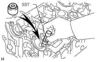
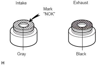
Using SST, push in a new oil seal.
- HINT:
-
The intake valve oil seal is gray and the exhaust valve oil seal is black.
- NOTICE:
-
Pay close attention when installing the intake and exhaust oil seals. For example, installing the intake oil seal into the exhaust or installing the exhaust oil seal to the intake can cause installation problems later.
13711
2.INSTALL INTAKE VALVE
Place the cylinder head on wooden blocks.
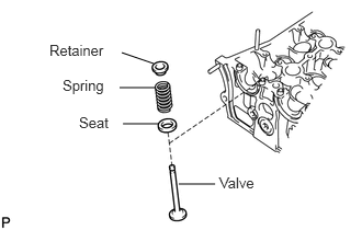
Install the valve, seat, spring and retainer onto the cylinder head.
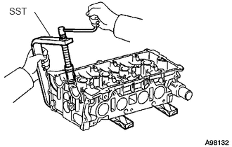
Using SST, compress the spring, and place the 2 retainer locks around the valve stem.
- SST
- 09202-70020 (09202-00010)
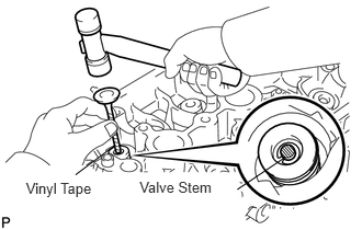
Using a plastic-faced hammer and discarded valve (with its tip wrapped with tape), lightly tap the installed valve to fit it into place.
- NOTICE:
-
Be careful not to damage the valve stem tip.
13715
3.INSTALL EXHAUST VALVE
Place the cylinder head on wooden blocks.
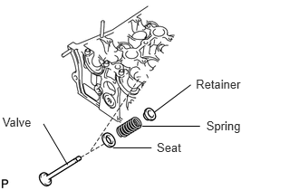
Install the valve, seat, spring and retainer onto the cylinder head.
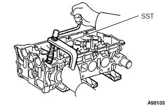
Using SST, compress the spring, and place the 2 retainer locks around the valve stem.
- SST
- 09202-70020 (09202-00010)
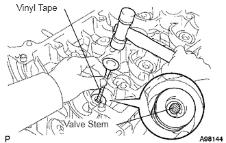
Using a plastic-faced hammer and discarded valve (with its tip wrapped with tape), lightly tap the installed valve to fit it into place.
- NOTICE:
-
Be careful not to damage the valve stem tip.
13751
4.INSTALL VALVE LIFTER
Assemble the valve lifter and the tip of the valve stem with a light coat of engine oil applied.
- NOTICE:
-
Install the valve lifters in their original places.
11811
5.INSTALL NO. 1 CAMSHAFT BEARING
Clean the contact surface of the bearing and the bearing cap.
- NOTICE:
-
Do not apply engine oil to the bearing or its contact surface.
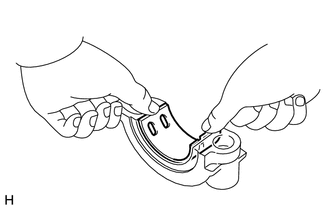
Align the bearing claw with the claw groove of the No. 1 and No. 2 bearing cap, and push in the No. 1 camshaft bearing.
11821
6.INSTALL NO. 2 CAMSHAFT BEARING
Clean the contact surface of the bearing and the cylinder head.
- NOTICE:
-
Do not apply engine oil to the bearing or its contact surface.
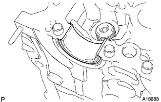
Install the No. 2 camshaft bearing onto the cylinder head.
11102A
7.INSTALL CAMSHAFT POSITION SENSOR
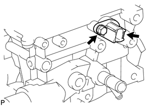
Install the sensor with the bolt.
- Torque:
- 9.0 N*m (92 kgf*cm, 80 in.*lbf)
8.INSTALL ENGINE COOLANT TEMPERATURE SENSOR
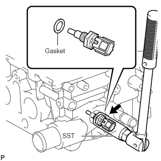
Using SST, install a new gasket and the ECT sensor.
- Torque:
- 20 N*m (204 kgf*cm, 15 ft.*lbf)
- SST
- 09817-33190
9.INSTALL OIL PRESSURE SWITCH
Apply adhesive to 2 or 3 threads of the oil pressure switch.
- Adhesive:
Toyota Genuine Adhesive 1344, Three Bond 1344 or Equivalent
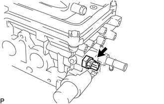
Using a 24 mm deep socket wrench, install the oil pressure switch.
- Torque:
- 13 N*m (133 kgf*cm, 10 ft.*lbf)
10.INSTALL RADIO SETTING CONDENSER
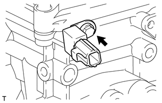
Install the condenser with the bolt.
- Torque:
- 10 N*m (102 kgf*cm, 7 ft.*lbf)