Home › Brake › BRAKE › BRAKE PEDAL › 2013.04–2014.09
RM24M0E _54 Brake _059558 BRAKE _0291874 BRAKE PEDAL N

BRAKE  BRAKE PEDAL  ADJUSTMENT  


PROCEDURE

Hide 1.CHECK AND ADJUST BRAKE PEDAL HEIGHT
a.
C200691E03
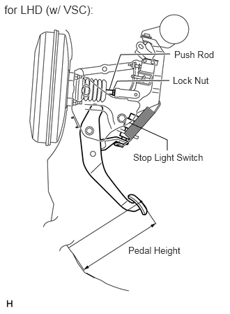
1.927,1.823 2.5,2.083 false 2.5,2.083 2.5,2.24 false 2.531,1.198 1.75,1.208 1.75,1.208 1.698,1.323 true 1.635,1.333 1.802,0.813 1.802,0.813 2.542,0.802 true 2.604,0.729 3.292,0.917 0.688,0.188 10 false Push Rod 2.583,1.115 3.208,1.292 0.625,0.177 10 false Lock Nut 1.99,2.26 3.135,2.448 1.146,0.188 10 false Stop Light Switch 0.063,0.042 1.729,0.281 1.667,0.24 12 false for LHD (w/ VSC): 1.917,3.646 2.802,3.875 0.885,0.229 10 false Pedal Height

C200693E02
1.938,1.844 2.49,2.135 false 2.5,2.135 2.5,2.292 false 2.521,1.24 1.885,1.24 1.885,1.24 1.844,1.354 true 1.74,1.344 1.969,0.625 1.969,0.625 2.427,0.625 true 2.573,1.156 3.198,1.333 0.625,0.177 10 false Lock Nut 2.073,2.333 3.219,2.521 1.146,0.188 10 false Stop Light Switch 2.156,3.969 3.042,4.198 0.885,0.229 10 false Pedal Height 0.135,0.125 3.229,0.615 3.094,0.49 12 true for LHD (w/o VSC): 2.479,0.542 3.188,0.917 0.708,0.375 10 true Push Rod

C200687E04
1.958,1.75 2.458,2.083 false 2.458,2.083 2.458,2.24 false 2.552,1.229 1.74,1.229 1.74,1.229 1.698,1.333 true 1.635,1.333 1.719,0.802 1.719,0.802 2.531,0.802 true 2.583,0.719 3.271,0.906 0.688,0.188 10 false Push Rod 2.604,1.156 3.229,1.333 0.625,0.177 10 false Lock Nut 2,2.271 3.146,2.458 1.146,0.188 10 false Stop Light Switch 0.094,0.063 1.583,0.375 1.49,0.313 12 false for RHD (w/ VSC): 2.313,3.479 3.198,3.708 0.885,0.229 10 false Pedal Height

C200689E02
1.979,1.76 2.469,2.083 false 2.469,2.083 2.469,2.25 false 2.542,1.24 1.885,1.24 1.885,1.24 1.844,1.365 true 1.729,1.354 1.896,0.823 1.896,0.823 2.552,0.823 true 2.594,0.75 3.281,0.938 0.688,0.188 10 false Push Rod 2.594,1.156 3.219,1.333 0.625,0.177 10 false Lock Nut 1.979,2.281 3.125,2.469 1.146,0.188 10 false Stop Light Switch 0.083,0.063 1.75,0.302 1.667,0.24 12 false for RHD (w/o VSC): 2.26,3.563 3.146,3.792 0.885,0.229 10 false Pedal Height

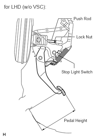
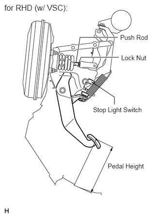
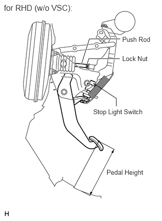
Check the pedal height.

Standard pedal height from dash panel:
Model Specified Condition
LHD (with VSC) 192.7 to 202.7 mm (7.587 to 7.980 in.)


Standard pedal height from dash panel:
Model Specified Condition
LHD (without VSC) 198.0 to 208.0 mm (7.795 to 8.189 in.)


Standard pedal height from dash panel:
Model Specified Condition
RHD (with VSC) 167.2 to 177.2 mm (6.583 to 6.976 in.)


Standard pedal height from dash panel:
Model Specified Condition
RHD (without VSC) 171.8 to 181.8 mm (6.764 to 7.158 in.)


b.

Adjust the pedal height.

i.

Disconnect the connector from the stop light switch.


ii.

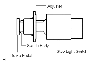
Turn the switch a quarter turn counterclockwise to remove the switch.


iii.

Loosen the lock nut.


iv.

Adjust the pedal height by turning the push rod.


v.

Tighten the lock nut.

Torque:
26 N*m (265 kgf*cm, 19 ft.*lbf)


vi.
C111301E12
0.74,1.115 0.74,1.563 false 2.313,1.344 2.313,1.656 false 1.229,0.5 1.229,0.198 1.229,0.198 1.573,0.198 false 0.604,1.188 0.604,1.792 false 0.74,1.563 0.885,1.563 false 1.615,0.125 2.333,0.323 0.719,0.198 10 false Adjuster 0.354,1.813 1.354,2.01 1,0.198 10 false Brake Pedal 1.927,1.667 3.063,1.875 1.135,0.208 10 false Stop Light Switch 0.917,1.479 1.74,1.688 0.823,0.208 10 false Switch Body

Insert the switch into the adjuster until the switch body touches the pedal.

NOTICE:

Do not depress the pedal.


vii.
C111302E13
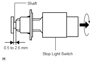
0.51,0.76 0.51,0.104 0.51,0.104 0.917,0.104 false 1.927,1.292 1.927,1.75 false 1.479,1.781 2.844,1.979 1.365,0.198 10 false Stop Light Switch 0.135,1.573 1.229,1.771 1.094,0.198 10 false 0.5 to 2.6 mm 0.958,0.031 1.396,0.229 0.438,0.198 10 false Shaft

Turn the switch a quarter turn clockwise.

Torque:
0.294 to 1.03 N*m (3.0 to 10.5 kgf*cm, 2.6 to 9.1 in.*lbf)

NOTICE:

Do not depress the pedal.


viii.

Connect the connector to the switch.


ix.

Check the switch clearance.

Standard stop light switch clearance:

0.5 to 2.6 mm (0.020 to 0.102 in.)


Hide 2.CHECK BRAKE PEDAL FREE PLAY

a.

Stop the engine. Depress the pedal several times until there is no vacuum in the booster. Then release the pedal.

b.
C111306E01
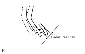
2.066,1.412 3.088,1.613 1.022,0.201 10 Pedal Free Play

Depress the pedal until resistance is felt.


c.

Check the pedal's free play by measuring the distance between the position in the previous step and the pedal's released position.

Standard pedal free play:

1.0 to 6.0 mm (0.039 to 0.236 in.)


If the free play is not as specified, check the switch clearance in the next step.

If the free play is as specified, proceed to the "CHECK BRAKE PEDAL RESERVE DISTANCE" procedure.


d.

Check the switch clearance.

Standard stop light switch clearance:

0.5 to 2.6 mm (0.020 to 0.102 in.)


If the clearance is not as specified, reinstall the switch and recheck the pedal's free play.

If the clearance is as specified, troubleshoot the brake system and proceed to the "CHECK BRAKE PEDAL RESERVE DISTANCE" procedure.


Hide 3.CHECK BRAKE PEDAL RESERVE DISTANCE

C111339E21
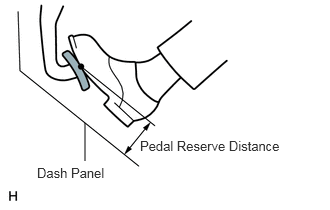
0.885,1.281 0.885,1.677 false 1.458,1.438 3.01,1.635 1.552,0.198 10 false Pedal Reserve Distance 0.385,1.719 1.188,1.917 0.802,0.198 10 false Dash Panel

a.

Release the parking brake lever. Start the engine.


b.

Depress the pedal and check the pedal reserve distance.

i.

Depress the pedal with a force of 490 N (50 kgf, 110 lbf).


ii.

Measure the distance between the pedal and dash panel shown in the illustration.

Standard pedal reserve distance:
Model Specified Condition
LHD (with VSC) More than 131 mm (5.16 in.)
LHD (without VSC) More than 117 mm (4.61 in.)
RHD (with VSC) More than 103 mm (4.06 in.)
RHD (without VSC) More than 92 mm (3.62 in.)


If the distance is not as specified, troubleshoot the brake system.