Home › Steering › STEERING COLUMN › STEERING LOCK SYSTEM
RM24M0E _55 Steering _059560 STEERING COLUMN _0291889 STEERING LOCK SYSTEM C

STEERING COLUMN  STEERING LOCK SYSTEM  B2788  IG2 Signal Malfunction  


DESCRIPTION

The steering lock ECU determines the on / off status of the engine switch through the IG2 signal circuit.

After receiving an IG2 relay ON signal, the steering lock ECU determines that the vehicle is moving.

The steering lock ECU does not lock the steering when it receives the IG2 relay ON signal. This prevents the steering from being locked while the vehicle is moving.

The diagnosis information of the steering lock ECU is transmitted to the tester via the certification ECU as the steering lock ECU is not connected to the CAN communication system.

DTC No. DTC Detection Condition Trouble Area
B2788 Open or short in IG2 signal circuit
·

Wire harness

·

Steering lock actuator (Steering lock ECU)

·

Main body ECU

·

IG2 relay circuit


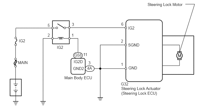
WIRING DIAGRAM

C136913E03
6.24,1.844 6.771,0.146 6.771,0.146 6.448,0.146 false 1.979,1.573 2.271,1.76 0.292,0.188 10 false IG2 0.656,1.344 0.948,1.531 0.292,0.188 10 false IG2 0.625,2.104 1.094,2.24 0.469,0.135 10 false MAIN 2.563,2.073 2.927,2.26 0.365,0.188 10 false IG2D 2.24,2.635 3.292,2.802 1.052,0.167 10 false Main Body ECU 4.458,1.49 4.927,1.677 0.469,0.188 10 false SGND 4.458,0.896 4.813,1.073 0.354,0.177 10 false IG2 4.469,2.292 4.854,2.531 0.385,0.24 10 false GND 4.208,2.854 5.635,3.552 1.427,0.698 10 false G32 5.135,0.073 6.406,0.281 1.271,0.208 10 false Steering Lock Motor 4.219,0.76 4.396,1 0.177,0.24 10 false 6 4.208,1.354 4.438,1.552 0.229,0.198 10 false 2 4.208,2.167 4.438,2.396 0.229,0.229 10 false 1 2.896,1.823 3.083,1.99 0.188,0.167 10 false 11 2.49,1.146 2.719,1.375 0.229,0.229 10 false 1 1.656,1.146 1.885,1.344 0.229,0.198 10 false 2 1.656,0.802 1.781,0.969 0.125,0.167 10 false 5 2.5,0.771 2.656,0.906 0.156,0.135 10 false 3 2.583,1.844 2.875,2 0.292,0.156 10 false G58 2.542,2.313 2.979,2.5 0.438,0.188 10 false GND2 3.031,2.302 3.25,2.448 0.219,0.146 10 false 4A 3.073,2.115 3.188,2.271 0.115,0.156 10 false 3 4.219,3.01 5.646,3.708 1.427,0.698 10 false Steering Lock Actuator (Steering Lock ECU)

CAUTION / NOTICE / HINT

HINT:

When the ignition switch is off, the main body ECU may occasionally go into a non-active state called sleep mode. Therefore, before proceeding with the inspection, it is necessary to perform the following step to wake up the ECU:

Before starting the inspection, with the ignition switch off, open the driver door. Then (with the ignition switch still off) open and close any door several times at 1.5 second intervals.


PROCEDURE
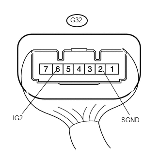
1.CHECK STEERING LOCK ACTUATOR (IG2 VOLTAGE)
U188605E02
2.208,1.51 2.781,2.469 false 1.219,1.5 0.479,2.438 false 0.271,2.448 0.844,2.677 0.573,0.229 10 false IG2 2.604,2.49 3.063,2.729 0.458,0.24 10 false SGND 1.51,0.344 1.865,0.573 0.354,0.229 10 false G32

a.

Measure the voltage of the steering lock actuator.

Standard voltage:
Tester Connection Condition Specified Condition
G32-6 (IG2) - G32-2 (SGND) Ignition switch on (IG) 10 to 14 V
G32-6 (IG2) - G32-2 (SGND) Ignition switch off Below 1 V


NG

2.INSPECT IGNITION RELAY NO. 2

OK

REPLACE STEERING LOCK ACTUATOR

2.INSPECT IGNITION RELAY NO. 2
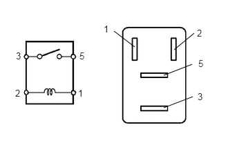
a.
B426341E07
2.625,0.75 2.927,0.5 false 2.469,1.135 2.896,0.969 false 2.469,1.625 2.906,1.458 false 2.031,0.708 1.719,0.469 false 0.24,0.76 0.458,0.979 0.219,0.219 10 false 3 0.229,1.323 0.448,1.542 0.219,0.219 10 false 2 1.198,0.76 1.417,0.979 0.219,0.219 10 false 5 1.177,1.323 1.396,1.542 0.219,0.219 10 false 1 1.563,0.354 1.781,0.573 0.219,0.219 10 false 1 2.99,0.875 3.208,1.094 0.219,0.219 10 false 5 2.979,1.375 3.198,1.594 0.219,0.219 10 false 3 2.969,0.417 3.188,0.635 0.219,0.219 10 false 2

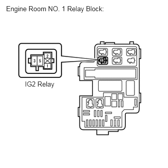
Remove the IG2 relay from the engine room No. 1 relay block.

b.

Measure the resistance of the relay.

Standard resistance:
Tester Connection Specified Condition
3 - 5 10 kΩ or higher
3 - 5 Below 1 Ω
(when battery voltage is applied to terminals 1 and 2)


OK

3.CHECK IG2 RELAY CIRCUIT (MAIN BODY ECU - IG2 RELAY AND BODY GROUND)

NG

REPLACE IGNITION RELAY NO. 2

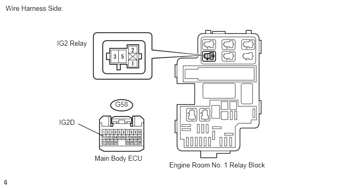
3.CHECK IG2 RELAY CIRCUIT (MAIN BODY ECU - IG2 RELAY AND BODY GROUND)
U188396E02
2.094,2.76 1.583,2.51 false 0.115,0.083 1.865,0.406 1.75,0.323 10 false Wire Harness Side: 3.427,3.26 5.552,3.5 2.125,0.24 10 false Engine Room No. 1 Relay Block 1.156,0.792 2.083,1.042 0.927,0.25 10 false IG2 Relay 1.917,3.125 3.021,3.375 1.104,0.25 10 false Main Body ECU 2.333,2.031 2.74,2.271 0.406,0.24 10 false G58 1.198,2.396 1.646,2.542 0.448,0.146 10 false IG2D

a.

Disconnect the G58 main body ECU connector.


b.

Remove the IG2 relay from the engine room No. 1 relay block.


c.

Measure the resistance of the wire harness side connectors.

Standard resistance:
Tester Connection Specified Condition
G58-11 (IG2D) - Relay block IG2 relay terminal 1 Below 1 Ω
G58-11 (IG2D) - Body ground 10 kΩ or higher
Relay block IG2 relay terminal 2 - Body ground Below 1 Ω


OK

4.CHECK MAIN BODY ECU (IG2D OPERATION)

NG

REPAIR OR REPLACE HARNESS OR CONNECTOR

4.CHECK MAIN BODY ECU (IG2D OPERATION)
a.

Connect the G58 main body ECU connector.


b.

Remove the IG2 relay from the engine room No. 1 relay block.


A137087E02
0.125,0.094 2.5,0.385 2.375,0.292 10 false Engine Room NO. 1 Relay Block: 0.51,1.635 1.208,1.875 0.698,0.24 10 false IG2 Relay

c.

Measure the voltage of the engine room No. 1 relay block IG2 relay terminal.

Standard voltage:
Tester Connection Condition Specified Condition
Relay block IG2 relay terminal 1 - Body ground Ignition switch on (IG) 10 to 14 V


OK

5.CHECK WIRE HARNESS (STEERING LOCK ECU - BATTERY)

NG

REPLACE MAIN BODY ECU

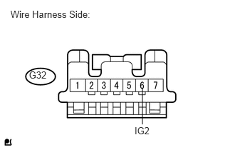
5.CHECK WIRE HARNESS (STEERING LOCK ECU - BATTERY)
a.
U188960E01
0.153,0.12 1.462,0.318 1.309,0.198 10 Wire Harness Side: 1.968,1.818 2.214,1.973 0.246,0.156 10 IG2 0.423,1.013 0.836,1.266 0.413,0.253 10 G32 2.083,1.28 2.083,1.813 false

Disconnect the G32 steering lock ECU connector.


b.

Measure the voltage of the wire harness side connector.

Standard voltage:
Tester Connection Condition Specified Condition
G32-6 (IG2) - Body ground Ignition switch on (IG) 10 to 14 V


OK

REPLACE STEERING LOCK ACTUATOR

NG

REPAIR OR REPLACE HARNESS OR CONNECTOR