RM24M0E
_55
Steering
_059561
POWER STEERING
_0291895
POWER STEERING SYSTEM
U
POWER STEERING POWER STEERING SYSTEM TERMINALS OF ECU
CHECK POWER STEERING ECU
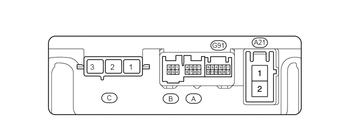
5.198,0.781 5.458,0.927
0.26,0.146
10
false
A21
4.344,0.844 4.646,0.99
0.302,0.146
10
false
G91
3.448,1.938 3.563,2.083
0.115,0.146
10
false
B
3.917,1.938 4.042,2.083
0.125,0.146
10
false
A
2.188,1.917 2.448,2.063
0.26,0.146
10
false
C
2.635,1.271 2.781,1.469
0.146,0.198
11
true
1
2.26,1.271 2.385,1.448
0.125,0.177
11
true
2
1.844,1.271 2.042,1.448
0.198,0.177
11
true
3
- HINT:
-
As connector C uses a lock lever, each terminal cannot be checked while the connector is still connected to the power steering ECU.
| Terminal No. (Symbols) | Wiring Color | Terminal Description |
|---|---|---|
| MV (C-1) | W | V phase motor output |
| MU (C-2) | B | U phase motor output |
| MW (C-3) | R | W phase motor output |
a.
Measure the voltage and resistance of the connectors.
- NOTICE:
-
When the P/S warning light is illuminated during a malfunction, the fail-safe function may cause the voltage of the power steering ECU's terminals to become 0 V.
| Terminal No. (Symbols) | Wiring Color | Terminal Description | Condition | Specified Condition |
|---|---|---|---|---|
| PIG (A21-1) - PGND (A21-2) | B - W | Power source | Always | 10 to 14 V |
| IG (G91-6) - PGND (A21-2) | R - W | IG power source | Ignition switch on (IG) | 10 to 14 V |
| TRQ1 (A-5) - TRQG (A-8) | W - B | Torque sensor signal | Ignition switch on (IG)
Steering wheel not turned (without load) |
2.3 to 2.7 V |
| Ignition switch on (IG)
Steering wheel turned to right with vehicle stopped |
2.5 to 3.8 V | |||
| Ignition switch on (IG)
Steering wheel turned to left with vehicle stopped |
1.2 to 2.5 V | |||
| TRQ2 (A-7) - TRQG (A-8) | Y - B | Torque sensor signal | Ignition switch on (IG)
Steering wheel not turned (without load) |
2.3 to 2.7 V |
| Ignition switch on (IG)
Steering wheel turned to right with vehicle stopped |
1.2 to 2.5 V | |||
| Ignition switch on (IG)
Steering wheel turned to left with vehicle stopped |
2.5 to 3.8 V | |||
| TRQV (A-6) - TRQG (A-8) | R - B | Torque sensor voltage source | Ignition switch on (IG) | 4.5 to 5.5 V |
| TRQG (A-8) - Body ground | B - Body ground | Torque sensor ground | Always | Below 1 Ω |
| PGND (A21-2) - Body ground | W - Body ground | Power ground | Always | Below 1 Ω |
| RZV (B-1) - PGND (A21-2) | R - W | Rotation angle sensor excitation output signal | Ignition switch on (IG)
Steering wheel is turned |
0.68 to 4.42 V |
| RZSN (B-6) - PGND (A21-2) | Y - W | Rotation angle sensor SIN aspect output signal | Ignition switch on (IG)
Steering wheel is turned |
0.68 to 4.42 V |
| RZCS (B-5) - PGND (A21-2) | L - W | Rotation angle sensor COS aspect output signal | Ignition switch on (IG)
Steering wheel is turned |
0.68 to 4.42 V |
| RZG (B-3) - PGND (A21-2) | B - W | Rotation angle sensor excitation circuit GND | Always | Below 1 Ω |
| CANH (G91-1) - CANL (G91-7) | Y - W | CAN communication line | Ignition switch off | 54 to 69 Ω |
If the result is not as specified, the ECU may have a malfunction.