RM24M0E
_58
Vehicle Interior
_059562
SUPPLEMENTAL RESTRAINT SYSTEMS
_0291898
AIRBAG SYSTEM
J
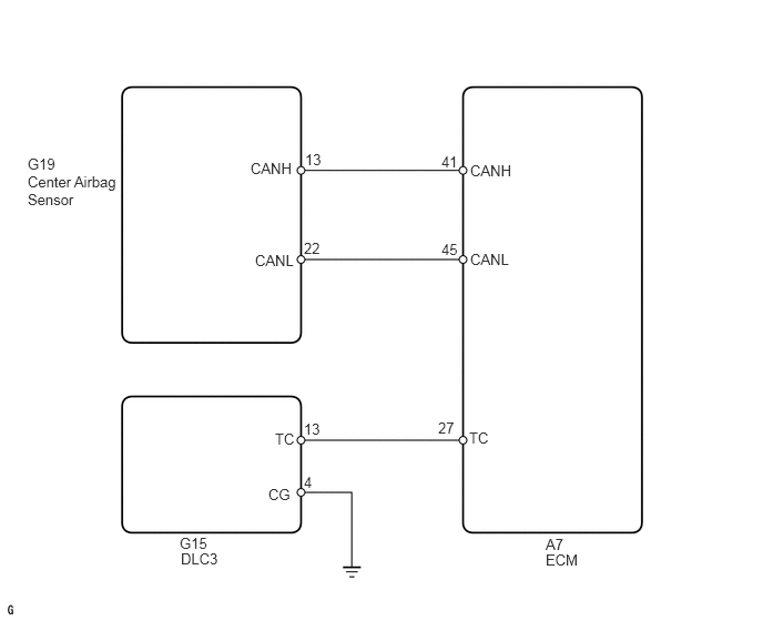
SUPPLEMENTAL RESTRAINT SYSTEMS AIRBAG SYSTEM TC and CG Terminal Circuit
DESCRIPTION
DTC output mode is set by connecting terminals TC and CG of the DLC3.
The DTCs are displayed by blinking the SRS warning light.
- HINT:
- ·
Make sure that DTC B1281 has not been output. If DTC B1281 has been output, refer to the multiplex communication system.
·When each warning light keeps blinking, a short to ground in the wiring of terminal TC of the DLC3 or an internal ground short in each ECU is suspected.
WIRING DIAGRAM
0.26,1.458 1.177,2.021
0.917,0.563
10
false
G19
1.688,5.021 2.115,5.333
0.427,0.313
10
false
G15
5.125,5.031 5.542,5.427
0.417,0.396
10
false
A7
2.354,1.5 2.823,1.667
0.469,0.167
10
false
CANH
2.396,2.365 2.865,2.531
0.469,0.167
10
false
CANL
4.417,1.521 4.885,1.688
0.469,0.167
10
false
CANH
4.146,1.438 4.354,1.604
0.208,0.167
10
false
41
4.146,2.26 4.354,2.427
0.208,0.167
10
false
45
2.865,1.417 3.073,1.583
0.208,0.167
10
false
13
2.854,2.25 3.063,2.417
0.208,0.167
10
false
22
2.854,3.948 3.063,4.115
0.208,0.167
10
false
13
2.854,4.448 3.063,4.615
0.208,0.167
10
false
4
4.115,3.938 4.323,4.104
0.208,0.167
10
false
27
4.417,2.354 4.885,2.521
0.469,0.167
10
false
CANL
2.583,4.042 2.813,4.198
0.229,0.156
10
false
TC
2.521,4.563 2.75,4.719
0.229,0.156
10
false
CG
4.406,4.031 4.635,4.188
0.229,0.156
10
false
TC
0.26,1.625 1.177,2.188
0.917,0.563
10
false
Center Airbag Sensor
5.125,5.177 5.542,5.573
0.417,0.396
10
false
ECM
1.698,5.167 2.125,5.479
0.427,0.313
10
false
DLC3
PROCEDURE
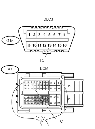
1.CHECK WIRE HARNESS (DLC3 - ECM)
a.
1.771,1.729 1.646,2.052
true
1.25,3.219 2.01,4.313
true
0.229,1.385 0.563,1.573
0.333,0.188
10
false
G15
0.281,2.427 0.49,2.604
0.208,0.177
10
false
A7
1.573,0.615 2,0.781
0.427,0.167
10
false
DLC3
1.448,2.396 1.875,2.563
0.427,0.167
10
false
ECM
1.427,2.104 1.677,2.271
0.25,0.167
10
false
TC
2.094,4.313 2.344,4.479
0.25,0.167
10
false
TC
Turn the ignition switch off.
b.
Disconnect the A7 ECM connector.
c.
Measure the resistance of the wire harness side connector.
- Standard resistance:
Tester Connection Specified Condition G15-13 (TC) - A7-27 (TC) Below 1 Ω A7-27 (TC) - Body ground 1 MΩ or higher
OK
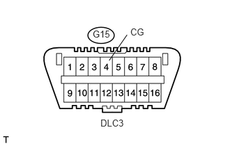
2.CHECK WIRE HARNESS (DLC3 - BODY GROUND)
NG
REPAIR OR REPLACE HARNESS OR CONNECTOR
2.CHECK WIRE HARNESS (DLC3 - BODY GROUND)
a.
1.948,0.392 2.223,0.577
0.276,0.185
10
CG
1.631,0.906 1.899,0.521
false
1.501,1.761 1.927,1.912
0.426,0.150
10
DLC3
1.385,0.426 1.673,0.589
0.288,0.163
10
G15
Measure the resistance of the wire harness side connector.
- Standard resistance:
Tester Connection Specified Condition G15-4 (CG) - Body ground Below 1 Ω
OK
3.CHECK ECM (OPERATION)
NG
REPAIR OR REPLACE HARNESS OR CONNECTOR
3.CHECK ECM (OPERATION)
a.
Temporarily replace the ECM with a new or normally functioning one.
b.
Check the DTC of the ECM.
| Result | Proceed to |
|---|---|
| DTC output mode is set (except center airbag sensor) | A |
| Normal system code is output | B |
| DTC is output | C |
A
REPAIR OR REPLACE WIRE HARNESS OR EACH ECU
B
END (ECM IS DEFECTIVE)
C
Go to DTC CHART