LIGHTING LIGHTING SYSTEM(except LED Headlight) TERMINALS OF ECU
CHECK MAIN BODY ECU (INSTRUMENT PANEL JUNCTION BLOCK LH)
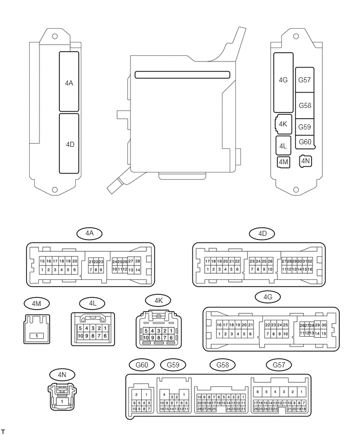
Disconnect the G59, 4A, 4D and 4K ECU connectors.
Measure the voltage and resistance of the wire harness side connectors.
| Symbols (Terminal No.) | Wiring Color | Terminal Description | Condition | Specified Condition |
|---|---|---|---|---|
| BATB (4K-9) - Body ground | B - Body ground | Battery power supply | Always | 10 to 14 V |
| ACC (4A-26) - Body ground | GR - Body ground | ACC power supply | Engine switch on (ACC) | 10 to 14 V |
| ACC (4A-26) - Body ground | GR - Body ground | ACC power supply | Engine switch off | Below 1 V |
| GND2 (4A-3) - Body ground | W-B - Body ground | Ground | Always | Below 1 Ω |
| GND1 (G59-1) - Body ground | W-B - Body ground | Ground | Always | Below 1 Ω |
If the result is not as specified, there may be a malfunction in the wire harness.
Reconnect the G59, 4A, 4D and 4K ECU connectors.
Measure the voltage of the connectors.
| Symbols (Terminal No.) | Wiring Color | Terminal Description | Condition | Specified Condition |
|---|---|---|---|---|
| DCTY (G57-24) - Body ground | L - Body ground | Driver side door courtesy switch input | Driver side door closed | 10 to 14 V |
| DCTY (G57-24) - Body ground | L - Body ground | Driver side door courtesy switch input | Driver side door open | Below 1 V |
| PCTY (G58-21) - Body ground | L - Body ground | Front passenger side door courtesy switch input | Front passenger side door closed | 10 to 14 V |
| PCTY (G58-21) - Body ground | L - Body ground | Front passenger side door courtesy switch input | Front passenger side door open | Below 1 V |
| LCTY (4A-4) - Body ground | BE - Body ground | Slide door LH courtesy light switch input | Slide door LH closed | 10 to 14 V |
| LCTY (4A-4) - Body ground | BE - Body ground | Slide door LH courtesy light switch input | Slide door LH open | Below 1 V |
| RCTY (G58-7) - Body ground | LG - Body ground | Slide door RH courtesy light switch input | Slide door RH closed | 10 to 14 V |
| RCTY (G58-7) - Body ground | LG - Body ground | Slide door RH courtesy light switch input | Slide door RH open | Below 1 V |
| BCTY (G58-25) - Body ground | W - Body ground | Back door courtesy light switch input | Back door closed | 10 to 14 V |
| BCTY (G58-25) - Body ground | W - Body ground | Back door courtesy light switch input | Back door open | Below 1 V |
| ACT+ (4D-5) - Body ground*1 | SB - Body ground | Driver side door lock motor LOCK drive output | Master switch (door control switch) or driver side door key cylinder LOCK | 10 to 14 V |
| ACT+ (4D-5) - Body ground*1 | SB - Body ground | Driver side door lock motor LOCK drive output | Master switch (door control switch) or driver side door key cylinder OFF | Below 1 V |
| ACT+ (4D-1) - Body ground*2 | R - Body ground | Driver side door lock motor LOCK drive output | Master switch (door control switch) or driver side door key cylinder LOCK | 10 to 14 V |
| ACT+ (4D-1) - Body ground*2 | R - Body ground | Driver side door lock motor LOCK drive output | Master switch (door control switch) or driver side door key cylinder OFF | Below 1 V |
| ACT- (4D-21) - Body ground*1 | W - Body ground | Driver side door lock motor UNLOCK drive output | Master switch (door control switch) or driver side door key cylinder UNLOCK | 10 to 14 V |
| ACT- (4D-21) - Body ground*1 | W - Body ground | Driver side door lock motor UNLOCK drive output | Master switch (door control switch) or driver side door key cylinder OFF | Below 1 V |
| ACT- (4D-20) - Body ground*2 | BE - Body ground | Driver side door lock motor UNLOCK drive output | Master switch (door control switch) or driver side door key cylinder UNLOCK | 10 to 14 V |
| ACT- (4D-20) - Body ground*2 | BE - Body ground | Driver side door lock motor UNLOCK drive output | Master switch (door control switch) or driver side door key cylinder OFF | Below 1 V |
| ACT+ (4D-1) - Body ground*1 | R - Body ground | Front passenger side door lock motor LOCK drive output | Master switch (door control switch) or driver side door key cylinder LOCK | 10 to 14 V |
| ACT+ (4D-1) - Body ground*1 | R - Body ground | Front passenger side door lock motor LOCK drive output | Master switch (door control switch) or driver side door key cylinder OFF | Below 1 V |
| ACT+ (4D-5) - Body ground*2 | SB - Body ground | Front passenger side door lock motor LOCK drive output | Master switch (door control switch) or driver side door key cylinder LOCK | 10 to 14 V |
| ACT+ (4D-5) - Body ground*2 | SB - Body ground | Front passenger side door lock motor LOCK drive output | Master switch (door control switch) or driver side door key cylinder OFF | Below 1 V |
| ACT- (4D-20) - Body ground*1 | O - Body ground | Front passenger side door lock motor UNLOCK drive output | Master switch (door control switch) or driver side door key cylinder UNLOCK | 10 to 14 V |
| ACT- (4D-20) - Body ground*1 | O - Body ground | Front passenger side door lock motor UNLOCK drive output | Master switch (door control switch) or driver side door key cylinder OFF | Below 1 V |
| ACT- (4D-21) - Body ground*2 | W - Body ground | Front passenger side door lock motor UNLOCK drive output | Master switch (door control switch) or driver side door key cylinder UNLOCK | 10 to 14 V |
| ACT- (4D-21) - Body ground*2 | W - Body ground | Front passenger side door lock motor UNLOCK drive output | Master switch (door control switch) or driver side door key cylinder OFF | Below 1 V |
| ACT+ (4G-7) - Body ground | Y - Body ground | Slide door LH lock motor LOCK drive output | Master switch (door control switch) or driver side door key cylinder LOCK | 10 to 14 V |
| ACT+ (4G-7) - Body ground | Y - Body ground | Slide door LH lock motor LOCK drive output | Master switch (door control switch) or driver side door key cylinder OFF | Below 1 V |
| ACT- (4G-23) - Body ground | L - Body ground | Slide door LH lock motor UNLOCK drive output | Master switch (door control switch) or driver side door key cylinder UNLOCK | 10 to 14 V |
| ACT- (4G-23) - Body ground | L - Body ground | Slide door LH lock motor UNLOCK drive output | Master switch (door control switch) or driver side door key cylinder OFF | Below 1 V |
| ACT+ (4D-4) - Body ground | GR - Body ground | Slide door RH lock motor LOCK drive output | Master switch (door control switch) or driver side door key cylinder LOCK | 10 to 14 V |
| ACT+ (4D-4) - Body ground | GR - Body ground | Slide door RH lock motor LOCK drive output | Master switch (door control switch) or driver side door key cylinder OFF | Below 1 V |
| ACT- (4D-21) - Body ground | W - Body ground | Slide door RH lock motor UNLOCK drive output | Master switch (door control switch) or driver side door key cylinder UNLOCK | 10 to 14 V |
| ACT- (4D-21) - Body ground | W - Body ground | Slide door RH lock motor UNLOCK drive output | Master switch (door control switch) or driver side door key cylinder OFF | Below 1 V |
| LSWD (G57-9) - Body ground | SB - Body ground | Driver side door lock position switch input | Driver side door LOCK | 10 to 14 V |
| LSWD (G57-9) - Body ground | SB - Body ground | Driver side door lock position switch input | Driver side door UNLOCK | Below 1 V |
| LSWL (4D-6) - Body ground | SB - Body ground | Slide door LH lock position switch input | Slide door LH LOCK | Pulse generation |
| LSWL (4D-6) - Body ground | SB - Body ground | Slide door LH lock position switch input | Slide door LH UNLOCK | Below 1 V |
| LSWR (G58-5) - Body ground | Y - Body ground | Slide door RH lock position switch input | Slide door RH LOCK | 10 to 14 V |
| LSWR (G58-5) - Body ground | Y - Body ground | Slide door RH lock position switch input | Slide door RH UNLOCK | Below 1 V |
| TAIL (G57-23) - Body ground | G - Body ground | TAIL signal | Headlight dimmer switch position OFF | Pulse generation |
| TAIL (G57-23) - Body ground | G - Body ground | TAIL signal | Headlight dimmer switch position TAIL | Below 1 V |
| HEAD (G58-17) - Body ground | V - Body ground | HEAD signal | Headlight dimmer switch position OFF | 10 to 14 V |
| HEAD (G58-17) - Body ground | V - Body ground | HEAD signal | Headlight dimmer switch position HEAD | Below 1 V |
| HRLY (4L-6) - Body ground | R - Body ground | HEAD signal | Headlight dimmer switch position OFF | 10 to 14 V |
| HRLY (4L-6) - Body ground | R - Body ground | HEAD signal | Headlight dimmer switch position HEAD | Below 1 V |
| DIM (4K-8) - Body ground | B - Body ground | High beam signal | Headlight dimmer switch position OFF | 10 to 14 V |
| DIM (4K-8) - Body ground | B - Body ground | High beam signal | Headlight dimmer switch position HEAD and BEAM | Below 1 V |
| HU (4D-10) - Body ground | P - Body ground | High beam signal | Headlight dimmer switch position OFF | Pulse generation |
| HU (4D-10) - Body ground | P - Body ground | High beam signal | Headlight dimmer switch position HEAD and BEAM | Below 1 V |
| A (G57-21) - Body ground | V - Body ground | AUTO signal | Headlight dimmer switch position OFF | 10 to 14 V |
| A (G57-21) - Body ground | V - Body ground | AUTO signal | Headlight dimmer switch position AUTO | Below 1 V |
| HF (G57-13) - Body ground | Y - Body ground | FLASH (Passing) signal | Headlight dimmer switch position OFF | 10 to 14 V |
| HF (G57-13) - Body ground | Y - Body ground | FLASH (Passing) signal | Headlight dimmer switch position FLASH | Below 1 V |
| FFOG (G58-28) - Body ground | LG - Body ground | Front fog light signal | Headlight dimmer switch position TAIL or HEAD, front fog light switch OFF | 10 to 14 V |
| FFOG (G58-28) - Body ground | LG - Body ground | Front fog light signal | Headlight dimmer switch position TAIL or HEAD, front fog light switch ON | Below 1 V |
| FFGO (G57-4) - Body ground | LG - Body gound | Front fog light signal | Headlight dimmer switch position TAIL or HEAD, front fog light switch OFF | 10 to 14 V |
| FFGO (G57-4) - Body ground | LG - Body ground | Front fog light signal | Headlight dimmer switch position TAIL or HEAD, front fog light switch ON | Below 1 V |
| RFOG (G58-9) - Body ground | L - Body ground | Rear fog light signal | Headlight dimmer switch position TAIL or HEAD, rear fog light switch OFF | Pulse generation |
| RFOG (G58-9) - Body ground | L - Body ground | Rear fog light signal | Headlight dimmer switch position TAIL or HEAD, rear fog light switch ON | Below 1 V |
| RFGO (G59-14) - Body ground | LG - Body ground | Rear fog light signal | Headlight dimmer switch position TAIL or HEAD, rear fog light switch OFF | 10 to 14 V |
| RFGO (G59-14) - Body ground | LG - Body ground | Rear fog light signal | Headlight dimmer switch position TAIL or HEAD, rear fog light switch ON | Below 1 V |
| DCYL (G57-25) - Body ground | LG*1 - Body ground
GR*2 - Body ground |
Front door courtesy light LH signal*1
Front door courtesy light RH signal*2 |
Front door LH open*1
Front door RH open*2 |
- |
| DCYL (G57-25) - Body ground | LG*1 - Body ground
GR*2 - Body ground |
Front door courtesy light LH signal*1
Front door courtesy light RH signal*2 |
Front door LH closed*1
Front door RH closed*2 |
- |
| PCYL (G58-11) - Body ground | GR*1 - Body ground
LG*2 - Body ground |
Front door courtesy light RH signal*1
Front door courtesy light LH signal*2 |
Front door RH open*1
Front door LH open*2 |
- |
| PCYL (G58-11) - Body ground | GR*1 - Body ground
LG*2 - Body ground |
Front door courtesy light RH signal*1
Front door courtesy light LH signal*2 |
Front door RH closed*1
Front door LH closed*2 |
- |
| BCYL (G57-19) - Body ground | R - Body ground | Luggage compartment room light signal | Luggage compartment room light switch OFF | - |
| BCYL (G57-19) - Body ground | R - Body ground | Luggage compartment room light signal | Luggage compartment room light switch ON | - |
| FSPT (G59-11) - Body ground | SB - Body ground | Inside handle illumination light signal | Door open | Below 1 V |
| FSPT (G59-11) - Body ground | SB - Body ground | Inside handle illumination light signal | Door closed | Voltage increases gradually |
| ILE (4D-2) - Body ground | Y - Body ground | Illumination signal | Door open | Below 1 V |
| ILE (4D-2) - Body ground | Y - Body ground | Illumination signal | Door closed | 10 to 14 V |
| HAZ (G59-4) - Body ground | GR - Body ground | Hazard switch signal | Hazard switch OFF | 10 to 14 V |
| HAZ (G59-4) - Body ground | GR - Body ground | Hazard switch signal | Hazard switch ON | Below 1 V |
| CLTB (G58-20) - Body ground | GR - Body ground | Automatic light control sensor power supply | Engine switch on (IG) | 10 to 14 V |
| CLTE (G58-18) - Body ground | LG - Body ground | Automatic light control sensor ground | Always | Below 1 V |
| CLTS (G58-19) - Body ground | B - Body ground | Automatic light control sensor signal | Engine switch on (IG), headlight dimmer switch AUTO position | Pulse generation
Waveform varies according to brightness |
- HINT:
-
*1: for LHD
-
*2: for RHD
If the result is not as specified, the ECU may have a malfunction.
CHECK TURN SIGNAL FLASHER RELAY
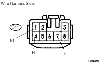
Measure the voltage of the connector.
| Symbols (Terminal No.) | Wiring Color | Terminal Description | Condition | Specified Condition |
|---|---|---|---|---|
| IG (G41-1) - Body ground | B - Body ground | Ignition power supply | Engine switch off | Below 1 V |
| IG (G41-1) - Body ground | B - Body ground | Ignition power supply | Engine switch on (IG) | 10 to 14 V |
| B (G41-4) - Body ground | P - Body ground | Battery power supply | Always | 10 to 14 V |
| E (G41-7) - Body ground | W-B - Body ground | Ground | Always | 10 to 14 V |
| EL (G41-5) - Body ground | Y*1 - Body ground
P*2 - Body ground |
Turn LH signal | Headlight dimmer switch NORMAL position | Below 1 V |
| EL (G41-5) - Body ground | Y*1 - Body ground
P*2 - Body ground |
Turn LH signal | Headlight dimmer switch TURN LH position | 10 to 14 V |
| LL (G41-3) - Body ground | V - Body ground | Turn LH signal | Headlight dimmer switch NORMAL position | Below 1 V |
| LL (G41-3) - Body ground | V - Body ground | Turn LH signal | Headlight dimmer switch TURN LH position | 10 to 14 V |
| ER (G41-6) - Body ground | G*1 - Body ground
SB*2 - Body ground |
Turn RH signal | Headlight dimmer switch NORMAL position | Below 1 V |
| ER (G41-6) - Body ground | G*1 - Body ground
SB*2 - Body ground |
Turn RH signal | Headlight dimmer switch TURN RH position | 10 to 14 V |
| LR (G41-2) - Body ground | Y - Body ground | Turn RH signal | Headlight dimmer switch NORMAL position | Below 1 V |
| LR (G41-2) - Body ground | Y - Body ground | Turn RH signal | Headlight dimmer switch TURN RH position | 10 to 14 V |
| HAZ (G41-8) - Body ground | GR - Body ground | Hazard switch signal | Hazard switch OFF | Below 1 V |
| HAZ (G41-8) - Body ground | GR - Body ground | Hazard switch signal | Hazard switch ON | 10 to 14 V |
- HINT:
-
*1: for LHD
-
*2: for RHD
If the result is not as specified, the relay may have a malfunction.
CHECK AFS ECU (w/ AFS)
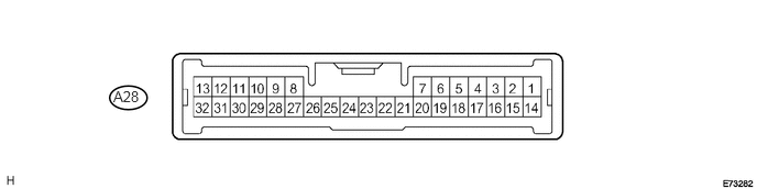
Disconnect the A28 ECU connector.
Measure the voltage and resistance of the wire harness side connector.
| Symbols (Terminal No.) | Wiring Color | Terminal Description | Condition | Specified Condition |
|---|---|---|---|---|
| IG (A28-15) - Body ground | B - Body ground | Ignition power supply | Engine switch off | Below 1 V |
| IG (A28-15) - Body ground | B - Body ground | Ignition power supply | Engine switch on (IG) | 10 to 14 V |
| IGS (A28-14) - Body ground | B - Body ground | Ignition power supply | Engine switch off | Below 1 V |
| IGS (A28-14) - Body ground | B - Body ground | Ignition power supply | Engine switch on (IG) | 10 to 14 V |
| E1 (A28-22) - Body ground | W-B - Body ground | Ground | Always | Below 1 Ω |
If the result is not as specified, the wire harness may have a malfunction.
Reconnect the A28 ECU connector.
Measure the voltage of the connectors.
| Symbols (Terminal No.) | Wiring Color | Terminal Description | Condition | Specified Condition |
|---|---|---|---|---|
| INIT (A28-7) - Body ground | BR - Body groubd | AFS operation check | Engine switch on (IG) | 5 V |
| CAN+ (A28-12) - Body ground | B - Body ground | CAN communication | Engine switch on (IG) | Pulse generation |
| CAN- (A28-13) - Body ground | W - Body ground | CAN communication | Engine switch on (IG) | Pulse generation |
| SML (A28-29) - Body ground | G - Body ground | Swivel actuator LH LIN communication | Engine switch on (IG) | Pulse generation |
| SMGL (A28-23) - Body ground | GR - Body ground | Swivel actuator LH ground | Always | Below 1 V |
| SMBL (A28-1) - Body ground | SB - Body ground | Swivel actuator LH power output | Engine switch on (IG) | 10 to 14 V |
| SMR (A28-10) - Body ground | L - Body ground | Swivel actuator RH LIN communication | Engine switch on (IG) | Pulse generation |
| SMGR (A28-24) - Body ground | Y - Body ground | Swivel actuator RH ground | Always | Below 1 V |
| SMBR (A28-2) - Body ground | BE - Body ground | Swivel actuator RH power output | Engine switch on (IG) | 10 to 14 V |
| LL1+ (A28-3) - Body ground | LG - Body ground | Headlight leveling motor LH power output | Engine switch on (IG) | 10 to 14 V |
| LL1- (A28-27) - Body ground | BE - Body ground | Headlight leveling motor LH ground | Always | Below 1 V |
| LHT (A28-30) - Body ground | V -Body ground | Headlight leveling motor LH LIN communication | Engine switch on (IG) | Pulse generation |
| LR1+ (A28-4) - Body ground | R - Body ground | Headlight leveling motor RH power output | Engine switch on (IG) | 10 to 14 V |
| LR1- (A28-28) - Body ground | BR - Body ground | Headlight leveling motor RH ground | Always | Below 1 V |
| RHT (A28-11) - Body ground | W*1 - Body ground
P*2 - Body ground |
Headlight leveling motor RH LIN communication | Engine switch on (IG) | Pulse generation |
| B (A28-18) - Body ground | V - Body ground | Height control sensor power output | Engine switch on (IG) | 5 V |
| SHRL (A28-19) - Body ground | GR - Body ground | Height control sensor signal | Engine switch on (IG)
(No occupants other than driver, vehicle is unloaded, vehicle is stopped) |
2.8 V |
| SGF (A28-21) - Body ground | B - Body ground | Height control sensor ground | Always | Below 1 V |
| MSW (A28-32) - Body ground | G - Body ground | AFS OFF switch input signal | Engine switch on (IG)
AFS OFF switch ON (cancel) |
Below 1 V |
| MSW (A28-32) - Body ground | G - Body ground | AFS OFF switch input signal | Engine switch on (IG)
AFS OFF switch OFF (normal) |
10 to 14 V |
- HINT:
-
*1: LHD 2GR-FE
-
*2: Except*1
If the result is not as specified, the ECU may have a malfunction.