Home › Vehicle Interior › LIGHTING › LIGHTING SYSTEM(except LED Headlight)
RM24M0E _58 Vehicle Interior _059564 LIGHTING _0291933 LIGHTING SYSTEM(except LED Headlight) J

LIGHTING  LIGHTING SYSTEM(except LED Headlight)  Headlight Beam Level Control Actuator Circuit  


DESCRIPTION

The headlight beam level control actuators are activated by operating the headlight leveling switch, allowing the headlight beam angle to be adjusted.

WIRING DIAGRAM
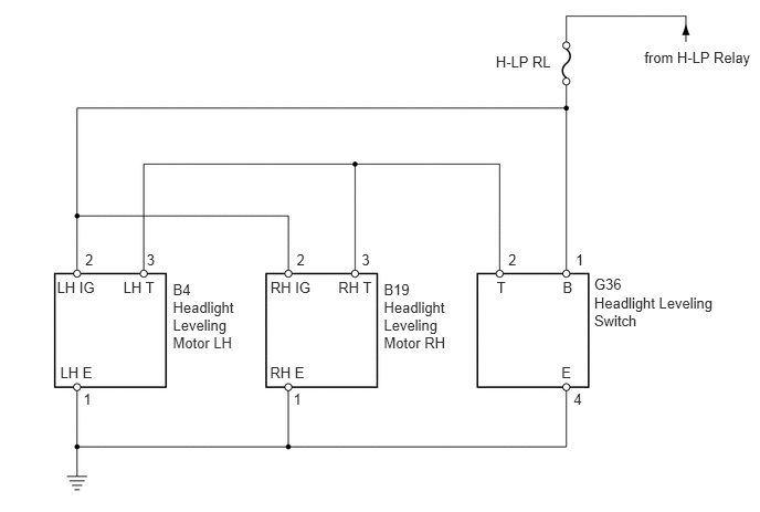
B132726E02
6.076,0.458 7.130,0.619 1.054,0.161 10 from H-LP Relay 4.675,0.502 5.294,0.649 0.619,0.147 10 H-LP RL 5.603,2.772 7.005,3.100 1.402,0.328 10 Headlight Leveling Switch 3.619,2.812 4.475,3.352 0.856,0.540 10 Headlight Leveling Motor RH 1.63,2.812 2.486,3.352 0.856,0.540 10 Headlight Leveling Motor LH 3.19,2.626 3.564,2.776 0.374,0.150 10 RH T 2.55,2.626 3.034,2.795 0.484,0.169 10 RH IG 2.546,3.431 3.022,3.606 0.476,0.175 10 RH E 5.306,2.626 5.553,2.786 0.246,0.159 10 B 5.428,2.365 5.674,2.524 0.246,0.159 10 1 4.793,2.365 5.039,2.524 0.246,0.159 10 2 2.797,2.365 3.044,2.524 0.246,0.159 10 2 3.619,2.645 4.016,2.804 0.397,0.159 10 B19 1.63,2.645 2.026,2.804 0.397,0.159 10 B4 3.41,2.365 3.657,2.524 0.246,0.159 10 3 0.803,2.365 1.049,2.524 0.246,0.159 10 2 1.383,2.365 1.630,2.524 0.246,0.159 10 3 5.409,3.682 5.655,3.841 0.246,0.159 10 4 2.766,3.682 3.012,3.841 0.246,0.159 10 1 0.786,3.682 1.032,3.841 0.246,0.159 10 1 5.603,2.598 6.015,2.758 0.411,0.159 10 G36 4.684,2.626 4.945,2.783 0.261,0.157 10 T 5.294,3.431 5.443,3.580 0.149,0.149 10 E 1.163,2.626 1.571,2.776 0.408,0.150 10 LH T 0.537,2.626 1.001,2.776 0.464,0.150 10 LH IG 0.568,3.431 0.931,3.589 0.364,0.158 10 LH E

PROCEDURE

1.CHECK TAILLIGHT
a.

Check that the taillight comes on when the light control switch is turned on (TAIL).

OK:

Taillight comes on.


OK

2.INSPECT HEADLIGHT LEVELING SWITCH

NG

GO TO TAILLIGHT RELAY CIRCUIT

2.INSPECT HEADLIGHT LEVELING SWITCH
E114455E03
2.2,2.816 2.657,2.997 0.457,0.181 10 Battery

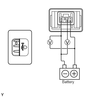
a.

Remove the headlight leveling switch.


b.

Connect the positive (+) battery lead to terminal 1 and the negative (-) battery lead to terminal 4.


c.

Check the ratio which is obtained by dividing the voltage between terminals 2 and 4 by the voltage between terminals 1 and 4. The voltages must be measured using a voltmeter.

Standard ratio:
Tester Connection Switch Position Specified Condition
1 (+B) - 4 (E) and 2 (T) - 4 (E) 0 0.87 to 0.93
1 (+B) - 4 (E) and 2 (T) - 4 (E) 1 0.76 to 0.82
1 (+B) - 4 (E) and 2 (T) - 4 (E) 2 0.66 to 0.72
1 (+B) - 4 (E) and 2 (T) - 4 (E) 3 0.55 to 0.61
1 (+B) - 4 (E) and 2 (T) - 4 (E) 4 0.44 to 0.50
1 (+B) - 4 (E) and 2 (T) - 4 (E) 5 0.34 to 0.40


OK

3.CHECK WIRE HARNESS (HEADLIGHT LEVELING SWITCH - BATTERY)

NG

REPLACE HEADLIGHT LEVELING SWITCH

3.CHECK WIRE HARNESS (HEADLIGHT LEVELING SWITCH - BATTERY)
U188628E02
1.323,1.573 0.865,1.833 false 0.115,0.073 1.635,0.24 1.521,0.167 10 false Wire Harness Side: 0.375,1.292 0.74,1.448 0.365,0.156 10 false G36 0.708,1.854 0.896,2.042 0.188,0.188 10 false B

a.

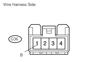
Disconnect the G36 headlight leveling switch connector.


b.

Measure the voltage of the wire harness side connector.

Standard voltage:
Tester Connection Condition Specified Condition
G36-1 (B) - Body ground Light control switch TAIL 10 to 14 V


OK

4.CHECK WIRE HARNESS (LEVELING SWITCH - LEVELING MOTOR AND BODY GROUND)

NG

REPAIR OR REPLACE HARNESS OR CONNECTOR

4.CHECK WIRE HARNESS (LEVELING SWITCH - LEVELING MOTOR AND BODY GROUND)
B460068E01
0.5,2.75 0.917,3 0.417,0.25 0.5,3.083 0.917,3.333 0.417,0.25 0.5,1.333 0.917,1.583 0.417,0.25 1.583,2.031 1.583,1.625 false 1.021,3.531 1.5,3.417 false 1.74,3.604 2.281,3.823 false 2.094,2.042 2.094,1.635 false 0.104,0.063 1.74,0.354 1.635,0.292 10 false Wire Harness Side: 1.552,2.083 2.063,2.385 0.51,0.302 10 false T 2.063,2.073 2.573,2.375 0.51,0.302 10 false E 0.573,1.365 1.083,1.667 0.51,0.302 10 false G36 0.896,0.583 2.573,0.875 1.677,0.292 10 false Headlight Leveling Switch 0.958,2.521 2.604,2.813 1.646,0.292 10 false Headlight Leveling Motor 0.969,2.771 1.479,3.073 0.51,0.302 10 false *1 0.969,3.115 1.479,3.417 0.51,0.302 10 false *2 0.615,2.781 1.125,3.083 0.51,0.302 10 false B4 0.573,3.115 1.083,3.417 0.51,0.302 10 false B19 0.552,3.469 1.146,3.76 0.594,0.292 10 false LH E*1 0.542,3.646 1.052,3.948 0.51,0.302 10 false RH E*2 2.333,3.75 2.917,4.042 0.583,0.292 10 false LH T*1 2.333,3.917 2.844,4.219 0.51,0.302 10 false RH T*2 0.156,4.052 0.938,4.313 0.781,0.26 10 false *1: for LH 0.156,4.323 0.885,4.625 0.729,0.302 10 false *2: for RH

a.

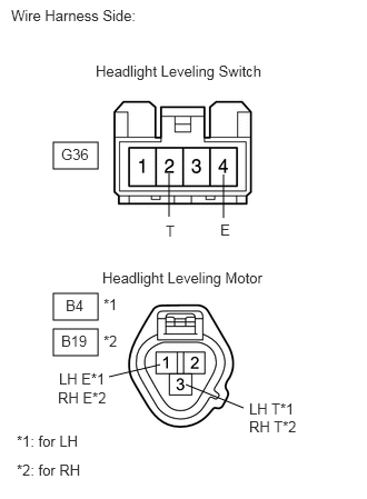
Disconnect the G36 headlight leveling switch connector.


b.

Disconnect the B4 and B19 headlight leveling motor connectors.


c.

Measure the resistance of the wire harness side connectors.

Standard resistance:
Tester Connection Specified Condition
G36-2 (T) - B4-3 (LH T) Below 1 Ω
G36-2 (T) or B4-3 (LH T) - Body ground 10 kΩ or higher
G36-2 (T) - B19-3 (RH T) Below 1 Ω
G36-2 (T) or B19-3 (RH T) - Body ground 10 kΩ or higher
G36-4 (E) - Body ground Below 1 Ω
B4-1 (LH E) - Body ground Below 1 Ω
B19-1 (RH E) - Body ground Below 1 Ω


OK

5.CHECK WIRE HARNESS (LEVELING MOTOR - BATTERY)

NG

REPAIR OR REPLACE HARNESS OR CONNECTOR

5.CHECK WIRE HARNESS (LEVELING MOTOR - BATTERY)
U188811E01
0.116,0.097 2.234,0.246 2.117,0.149 10 Wire Harness Side: 0.459,0.645 0.713,0.794 0.253,0.149 10 B4 0.312,2.484 0.965,2.633 0.653,0.149 10 *1: for LH 0.312,2.927 0.965,3.076 0.653,0.149 10 *2: for RH 0.854,0.641 1.506,0.790 0.653,0.149 10 *1 0.854,1.084 1.506,1.233 0.653,0.149 10 *2 2.45,1.971 2.955,2.120 0.504,0.149 10 LHIG*1 2.45,2.178 2.955,2.328 0.504,0.149 10 RHIG*2 0.411,1.088 0.684,1.237 0.273,0.149 10 B19 1.914,2.154 2.428,2.154 false

a.

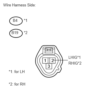
Disconnect the B4 and B19 headlight leveling motor connectors.


b.

Measure the voltage of the wire harness side connector.

Standard voltage:
Tester Connection Condition Specified Condition
B4-2 (LHIG) - Body ground Light control switch TAIL 10 to 14 V
B19-2 (RHIG) - Body ground Light control switch TAIL 10 to 14 V


OK

REPLACE HEADLIGHT LEVELING MOTOR

NG

REPAIR OR REPLACE HARNESS OR CONNECTOR