Home › Vehicle Interior › LIGHTING › LIGHTING SYSTEM(except LED Headlight)
RM24M0E _58 Vehicle Interior _059564 LIGHTING _0291933 LIGHTING SYSTEM(except LED Headlight) J

LIGHTING  LIGHTING SYSTEM(except LED Headlight)  Rear Fog Light Circuit  


DESCRIPTION

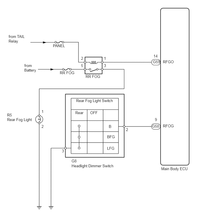
The main body ECU controls the rear fog light relay (marking: RR FOG) when a signal is received from the headlight dimmer switch.

WIRING DIAGRAM
E132457E02
5.865,6.031 6.958,6.198 1.094,0.167 10 false Main Body ECU 1.927,1.573 2.448,1.729 0.521,0.156 10 false PANEL 5.927,2.156 6.563,2.313 0.635,0.156 10 false RFGO 3.115,2.688 3.76,2.833 0.646,0.146 10 false RR FOG 0.885,2.292 1.375,2.625 0.49,0.333 10 false from Battery 2.177,2.552 2.844,2.708 0.667,0.156 10 false RR FOG 0.313,1.24 1.063,1.573 0.75,0.333 10 false from TAIL Relay 0.26,4.25 1.208,4.417 0.948,0.167 10 false Rear Fog Light 0.26,4.083 1.208,4.25 0.948,0.167 10 false R5 1.51,3.958 1.927,4.125 0.417,0.167 10 false 1 1.51,4.5 1.927,4.667 0.417,0.167 10 false 2 2.25,5.385 2.365,5.552 0.115,0.167 10 false 3 4.583,4.615 4.698,4.781 0.115,0.167 10 false 2 2.948,2.031 3.063,2.198 0.115,0.167 10 false 2 3.781,2.031 3.896,2.198 0.115,0.167 10 false 1 2.948,2.292 3.063,2.458 0.115,0.167 10 false 5 3.781,2.292 3.896,2.458 0.115,0.167 10 false 3 5.563,2.156 5.844,2.323 0.281,0.167 10 false G59 5.583,1.948 5.792,2.115 0.208,0.167 10 false 14 5.531,4.49 5.813,4.656 0.281,0.167 10 false G58 5.635,4.25 5.75,4.417 0.115,0.167 10 false 9 2.771,3.563 4.229,3.74 1.458,0.177 10 false Rear Fog Light Switch 3.281,4 3.625,4.156 0.344,0.156 10 false OFF 3.958,4.5 4.135,4.667 0.177,0.167 10 false B 3.896,4.875 4.208,5.021 0.313,0.146 10 false BFG 3.896,5.292 4.208,5.438 0.313,0.146 10 false LFG 2.604,5.75 4.25,5.917 1.646,0.167 10 false G8 2.604,5.927 4.25,6.094 1.646,0.167 10 false Headlight Dimmer Switch 5.927,4.479 6.448,4.635 0.521,0.156 10 false RFOG 2.74,4 3.135,4.156 0.396,0.156 10 false Rear

PROCEDURE

1.PERFORM ACTIVE TEST USING INTELLIGENT TESTER (REAR FOG LIGHT)
a.

Connect the intelligent tester to the DLC3.


b.

Turn the ignition switch on (IG) position and press the intelligent tester main switch ON.


c.

Select the item below in the Active Test and then check that the relay operates.

Main body ECU
Item Test Details Diagnostic Note
Rear Fog Light Relay Turn rear fog light relay: ON / OFF Headlight dimmer switch ON

OK:

Rear fog light comes on.


NG

2.CHECK TAILLIGHT

OK

10.INSPECT HEADLIGHT DIMMER SWITCH ASSEMBLY (REAR FOG LIGHT SWITCH)
2.CHECK TAILLIGHT
a.

Check that the taillights come on when the light control switch is turned on (TAIL).

OK:

Taillights come on.


OK

3.INSPECT FUSE (RR FOG, PANEL)

NG

GO TO TAILLIGHT RELAY CIRCUIT

3.INSPECT FUSE (RR FOG, PANEL)
a.

Remove the RR FOG fuse from the instrument panel junction block RH.


b.

Remove the PANEL fuse from the main body ECU.


c.

Measure the resistance of the fuses.

Standard resistance:

Below 1 Ω


OK

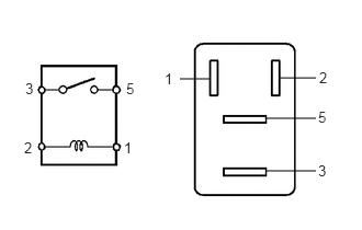
4.INSPECT REAR FOG LIGHT RELAY (Marking: RR FOG)

NG

REPLACE FUSE

4.INSPECT REAR FOG LIGHT RELAY (Marking: RR FOG)
B426341E10
2.646,0.74 3,0.74 false 2.531,1.125 3,1.125 false 2.531,1.625 3,1.625 false 1.708,0.75 2,0.75 false 0.24,0.76 0.458,0.979 0.219,0.219 10 false 3 0.229,1.323 0.448,1.542 0.219,0.219 10 false 2 1.198,0.76 1.417,0.979 0.219,0.219 10 false 5 1.177,1.323 1.396,1.542 0.219,0.219 10 false 1 1.563,0.667 1.781,0.885 0.219,0.219 10 false 1 3.021,1.031 3.24,1.25 0.219,0.219 10 false 5 3.021,1.542 3.24,1.76 0.219,0.219 10 false 3 3.031,0.656 3.25,0.875 0.219,0.219 10 false 2

a.

Remove the rear fog light relay from the fusible link block.


b.

Measure the resistance of the relay.

Standard resistance:
Tester Connection Specified Condition
3 - 5 10 kΩ or higher
3 - 5 Below 1 Ω
(Battery voltage applied to terminals 1 and 2)


OK

5.REPLACE REAR FOG LIGHT BULB

NG

REPLACE REAR FOG LIGHT RELAY

5.REPLACE REAR FOG LIGHT BULB
a.

Replace the rear fog light bulb with a new one.


b.

Check that the bulb illuminates normally.

OK:

Bulb illuminates.


NG

6.INSPECT REAR FOG LIGHT ASSEMBLY

OK

END

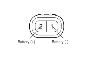
6.INSPECT REAR FOG LIGHT ASSEMBLY
a.
E133904E01
0.645,1.437 1.359,1.637 0.714,0.200 10 Battery (+) 1.894,1.437 2.608,1.637 0.714,0.200 10 Battery (-) 1.482,0.963 1.093,1.401 false 1.921,0.963 2.311,1.401 false

Remove the rear fog light.


b.

Connect the positive (+) lead from the battery to terminal 2 and the negative (-) lead to terminal 1. Then check that the bulb illuminates.

OK:

Bulb illuminates.


OK

7.CHECK WIRE HARNESS (MAIN BODY ECU - BATTERY)

NG

REPLACE REAR FOG LIGHT ASSEMBLY

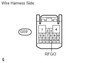
7.CHECK WIRE HARNESS (MAIN BODY ECU - BATTERY)
U188721E01
0.052,0.017 1.411,0.173 1.360,0.156 10 Wire Harness Side: 1.555,1.796 2.010,1.952 0.455,0.156 10 RFGO 0.697,1.015 0.977,1.196 0.280,0.181 10 G59 1.789,1.44 1.789,1.787 false

a.

Disconnect the G59 ECU connector.


b.

Measure the voltage of the wire harness side connector.

Standard voltage:
Tester Connection Condition Specified Condition
G59-14 (RFGO) - Body ground Light control switch on (TAIL) 10 to 14 V


OK

8.CHECK WIRE HARNESS (REAR FOG LIGHT RELAY - BATTERY)

NG

REPAIR OR REPLACE HARNESS OR CONNECTOR

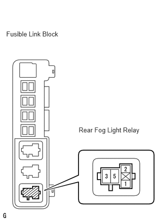
8.CHECK WIRE HARNESS (REAR FOG LIGHT RELAY - BATTERY)
B141166E01
1.66,2.669 3.016,2.845 1.356,0.176 10 Rear Fog Light Relay 0.132,0.633 1.495,0.809 1.363,0.176 10 Fusible Link Block

a.

Remove the rear fog light relay from the fusible link block.


b.

Measure the voltage of the relay block.

Standard voltage:
Tester Connection Specified Condition
Fusible link block rear fog light relay terminal 5 - Body ground 10 to 14 V


OK

9.CHECK WIRE HARNESS (REAR FOG LIGHT - REAR FOG LIGHT RELAY AND BODY GROUND)

NG

REPAIR OR REPLACE HARNESS OR CONNECTOR

9.CHECK WIRE HARNESS (REAR FOG LIGHT - REAR FOG LIGHT RELAY AND BODY GROUND)
U188741E02
5.542,2.229 6.906,2.406 1.365,0.177 10 false Rear Fog Light Relay 0.073,0.01 1.396,0.167 1.323,0.156 10 false Wire Harness Side: 1.323,1.365 2.521,1.521 1.198,0.156 10 false Rear Fog Light 4.083,0.604 5.281,0.76 1.198,0.156 10 false Fusible Link Block 0.969,2.073 1.167,2.25 0.198,0.177 10 false R5

a.

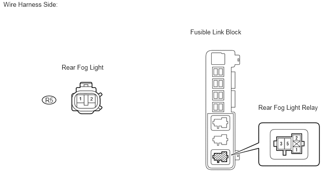
Disconnect the R5 rear fog light connector.


b.

Remove the rear fog light relay from the fusible link block.


c.

Measure the resistance of the wire harness side connectors and relay block.

Standard resistance:
Tester Connection Specified Condition
R5-1 - Relay block rear fog light relay terminal 3 Below 1 Ω
R5-1 or relay block rear fog light relay terminal 3 - Body ground 10 kΩ or higher
R5-2 - Body ground Below 1 Ω


OK

REPLACE MAIN BODY ECU

NG

REPAIR OR REPLACE HARNESS OR CONNECTOR

10.INSPECT HEADLIGHT DIMMER SWITCH ASSEMBLY (REAR FOG LIGHT SWITCH)
E068152E40
2.302,0.979 2.302,0.354 false 2.115,0.948 1.979,0.354 false 2.26,0.156 2.375,0.313 0.115,0.156 10 false B 1.646,0.156 2.01,0.313 0.365,0.156 10 false LFG

a.

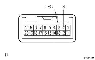
Remove the headlight dimmer switch.


b.

Measure the resistance of the switch.


Standard resistance:
Tester Connection Condition Specified Condition
2 (B) - 3 (LFG) Fog light switch OFF 10 kΩ or higher
2 (B) - 3 (LFG) Fog light switch ON Below 1 Ω


OK

11.CHECK WIRE HARNESS (DIMMER SWITCH - MAIN BODY ECU AND BODY GROUND)

NG

REPLACE HEADLIGHT DIMMER SWITCH ASSEMBLY

11.CHECK WIRE HARNESS (DIMMER SWITCH - MAIN BODY ECU AND BODY GROUND)
a.
U188734E02
2.635,1.427 2.292,1.427 2.292,1.427 2.083,1.625 false 1.229,3.813 1.031,3.5 1.031,3.5 0.604,3.5 false 1.365,3.823 1.573,3.5 1.573,3.5 2.552,3.5 false 0.083,0.021 1.469,0.177 1.385,0.156 10 false Wire Harness Side: 1.042,0.542 2.24,0.698 1.198,0.156 10 false Main Body ECU 0.698,2.885 2.313,3.042 1.615,0.156 10 false Headlight Dimmer Switch 2.667,1.323 3.104,1.479 0.438,0.156 10 false RFOG 0.521,3.719 0.719,3.896 0.198,0.177 10 false G8 0.49,1.615 0.771,1.792 0.281,0.177 10 false G58 0.438,3.417 0.583,3.573 0.146,0.156 10 false B 2.604,3.417 2.938,3.573 0.333,0.156 10 false LFG

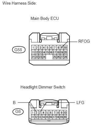
Disconnect the G8 headlight dimmer switch connector.


b.

Disconnect the G58 main body ECU connector.


c.

Measure the resistance of the wire harness side connectors.

Standard resistance:
Tester Connection Specified Condition
G8-2 (B) - G58-9 (RFOG) Below 1 Ω
G8-2 (B) or G58-9 (RFOG) - Body ground 10 kΩ or higher
G8-3 (LFG) - Body ground Below 1 Ω


OK

PROCEED TO NEXT CIRCUIT INSPECTION SHOWN IN PROBLEM SYMPTOMS TABLE

NG

REPAIR OR REPLACE HARNESS OR CONNECTOR