RM24M0E
_58
Vehicle Interior
_059564
LIGHTING
_0291948
TURN SIGNAL FLASHER ASSEMBLY
G
LIGHTING TURN SIGNAL FLASHER ASSEMBLY ON-VEHICLE INSPECTION
PROCEDURE

 1.INSPECT TURN SIGNAL FLASHER CIRCUIT
1.177,1 0.552,1.323
false
1.188,1.333 1.156,1.698
false
2.021,1.323 2.229,1.74
false
0.052,0.24 1.656,0.438
1.604,0.198
10
false
Wire Harness Side:
0.396,0.865 0.76,1.052
0.365,0.188
10
false
G41
0.385,1.302 0.792,1.448
0.406,0.146
10
false
IG
1.104,1.74 1.26,1.885
0.156,0.146
10
false
B
2.188,1.771 2.323,1.917
0.135,0.146
10
false
E
a.
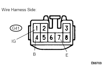
Check the power source circuit and ground circuit.
i.
Remove the turn signal flasher assembly.
ii.
Measure the voltage and resistance of the wire harness side connector.
- Standard Voltage:
Tester Connection Condition Specified Condition G41-1 (IG) - Body ground Ignition switch off 0 V G41-1 (IG) - Body ground Ignition switch on (IG) 10 to 14 V G41-4 (B) - Body ground Always 10 to 14 V
- Standard Resistance:
Tester Connection Condition Specified Condition G41-7 (E) - Body ground Always Below 1 Ω
If the result is not as specified, replace the turn signal flasher.
b.
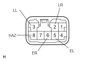
Check the output operation signal.
i.
2,0.854 2.167,0.281
false
1.125,0.917 0.708,0.354
false
2.01,1.375 2.479,1.719
false
1.708,1.365 1.375,1.813
false
1.146,1.26 0.604,1.26
false
2.104,0.094 2.313,0.323
0.208,0.229
10
false
LR
0.469,0.281 0.802,0.531
0.333,0.25
10
false
LL
2.521,1.74 2.927,1.927
0.406,0.188
10
false
EL
1.156,1.813 1.521,1.958
0.365,0.146
10
false
ER
0.313,1.188 0.688,1.448
0.375,0.26
10
false
HAZ
Install the turn signal flasher relay.
ii.
Measure the voltage of the turn signal flasher relay.
- Standard:
Tester Connection Condition Specified Condition 2 (LR) - Body ground Hazard warning switch OFF → ON 0 V → 10 to 14 V (60 to 120 times per minute) 2 (LR) - Body ground Turn signal switch (right turn) OFF → ON 0 V → 10 to 14 V (60 to 120 times per minute) 3 (LL) - Body ground Hazard warning switch OFF → ON 0 V → 10 to 14 V (60 to 120 times per minute) 3 (LL) - Body ground Turn signal switch (left turn) OFF → ON 0 V → 10 to 14 V (60 to 120 times per minute) 5 (EL) - Body ground Turn signal switch (left turn) OFF → ON 10 to 14 V → 0 V 6 (ER) - Body ground Turn signal switch (right turn) OFF → ON 10 to 14 V → 0 V 8 (HAZ) - Body ground Hazard warning switch OFF → ON 10 to 14 V → 0 V
If the result is not as specified, replace the turn signal flasher relay.