RM24M0E
_58
Vehicle Interior
_059564
LIGHTING
_0291960
STOP LIGHT CONTROL RELAY
G
LIGHTING STOP LIGHT CONTROL RELAY INSPECTION
PROCEDURE

 895A0
1.INSPECT STOP LIGHT CONTROL RELAY
a.
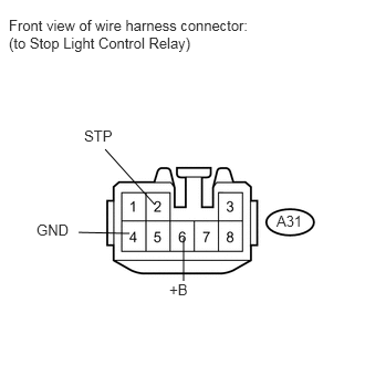
1.219,2.198 0.74,2.188
false
1.729,2.24 1.729,2.646
false
1.458,1.927 0.99,1.406
false
2.604,2 2.896,2.208
0.292,0.208
10
false
A31
0.083,0.156 2.458,0.531
2.375,0.375
10
false
Front view of wire harness connector: (to Stop Light Control Relay)
0.792,1.198 1.094,1.406
0.302,0.208
10
false
STP
1.594,2.646 1.823,2.854
0.229,0.208
10
false
+B
0.344,2.083 0.667,2.292
0.323,0.208
10
false
GND
Disconnect the A31 stop light control relay connector.
b.
Measure the voltage according to the value(s) in the table below.
- Standard Voltage:
Tester Connection Condition Specified Condition A31-2 (STP) - Body ground Brake pedal released Below 1 V Brake pedal depressed 11 to 14 V A31-6 (+B) - Body ground Always 11 to 14 V
If the result is not as specified, repair or replace the wire harness or connector.
c.
Measure the resistance according to the value(s) in the table below.
- Standard Resistance:
Tester Connection Condition Specified Condition A31-4 (GND) - Body ground Always Below 1 Ω
If the result is not as specified, repair or replace the wire harness or connector.
d.
0.126,0.079 2.449,0.422
2.323,0.343
10
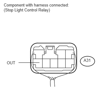
Component with harness connected: (Stop Light Control Relay)
0.227,2.027 0.555,2.195
0.328,0.168
10
OUT
2.818,1.945 3.107,2.113
0.290,0.168
10
A31
1.329,2.111 0.625,2.111
false
Reconnect the A31 stop light control relay connector.
e.
Measure the voltage according to the value(s) in the table below.
- Standard Voltage:
Tester Connection Condition Specified Condition A31-8 (OUT) - Body ground Brake pedal released Below 1 V Brake pedal depressed 11 to 14 V
If the result is not as specified, replace the stop light control relay.