LIGHTING LIGHTING SYSTEM(for LED Headlight) TERMINALS OF ECU
CHECK MAIN BODY ECU
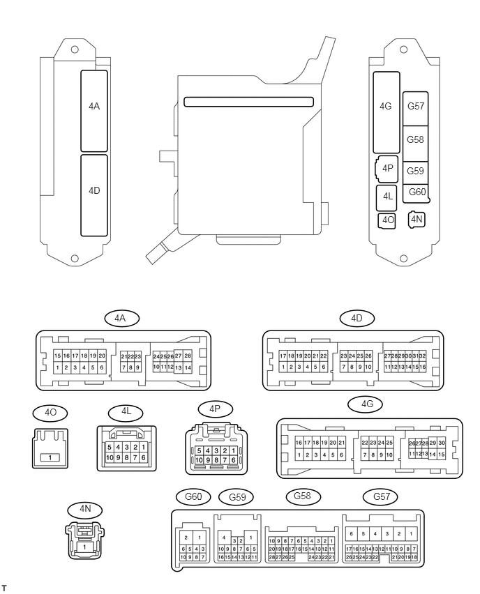
Inspect the main body ECU.
Measure the voltage and resistance of the wire harness side connectors.
| Terminal No. (Symbols) | Wiring Color | Terminal Description | Condition | Specified Condition |
|---|---|---|---|---|
| 4A-3 (GND2) - Body ground | W-B - Body ground | Ground | Always | Below 1 Ω |
| 4A-4 (LCTY) - Body ground | BE - Body ground | Slide door LH courtesy light switch input | Slide door LH closed | Pulse generation |
| Slide door LH open | Below 1 V | |||
| 4A-5 - Body ground | W-B - Body ground | Ground | Always | Below 1 Ω |
| 4A-16 (TRLY) - Body ground | BR - Body ground | Taillight RH drive output | Headlight dimmer switch position OFF | Below 1 V |
| Headlight dimmer switch position TAIL | 11 to 14 V | |||
| 4A-26 (ACC) - Body ground | GR - Body ground | ACC power supply | Engine switch off | Below 1 V |
| Engine switch on (ACC) | 11 to 14 V |
| Terminal No. (Symbols) | Wiring Color | Terminal Description | Condition | Specified Condition |
|---|---|---|---|---|
| 4D-2 (ILE) - Body ground | Y - Body ground | Illumination signal | Map light off (when operated by illuminated entry system) | 11 to 14 V |
| Map light on (when operated by illuminated entry system) | Below 1 V | |||
| 4D-6 (LSWL) - Body ground | SB - Body ground | Slide door LH lock position switch input | Slide door LH LOCK | Pulse generation |
| Slide door LH UNLOCK | Below 1 V | |||
| 4D-10 (HU) - Body ground | P - Body ground | High beam signal | Headlight dimmer switch position HEAD and lo beam | Pulse generation |
| Headlight dimmer switch position HEAD and high beam | Below 1 V | |||
| 4D-13 (PKB) - Body ground | V - Body ground | Parking brake switch input | Parking brake switch off | 11 to 14 V |
| Parking brake switch ON | Below 1 V |
| Terminal No. (Symbols) | Wiring Color | Terminal Description | Condition | Specified Condition |
|---|---|---|---|---|
| 4G-10 (IG) - Body ground | R - Body ground | IG power supply | Engine switch off | Below 1 V |
| Engine switch on (IG) | 11 to 14 V | |||
| 4G-11 (IG) - Body ground | L - Body ground | IG power supply | Engine switch off | Below 1 V |
| Engine switch on (IG) | 11 to 14 V | |||
| 4G-30 (TRLY) - Body ground | BR - Body ground | Taillight LH drive output | Headlight dimmer switch position OFF | Below 1 V |
| Headlight dimmer switch position TAIL | 11 to 14 V |
| Terminal No. (Symbols) | Wiring Color | Terminal Description | Condition | Specified Condition |
|---|---|---|---|---|
| 4P-6 (IG) - Body ground | B - Body ground | IG power supply | Engine switch off | Below 1 V |
| Engine switch on (IG) | 11 to 14 V | |||
| 4P-8 (DIM) - Body ground | W - Body ground | High beam signal | Headlight dimmer switch position HEAD and lo beam | 11 to 14 V |
| Headlight dimmer switch position HEAD and high beam | Below 1 V |
| Terminal No. (Symbols) | Wiring Color | Terminal Description | Condition | Specified Condition |
|---|---|---|---|---|
| 4L-1 (TRLY) - Body ground | BR - Body ground | Clearance light RH drive output | Headlight dimmer switch position OFF | Below 1 V |
| Headlight dimmer switch position TAIL | 11 to 14 V | |||
| 4L-3 (TRLY) - Body ground | BR - Body ground | Clearance light LH drive output | Headlight dimmer switch position OFF | Below 1 V |
| Headlight dimmer switch position TAIL | 11 to 14 V | |||
| 4L-5 (TRLY) - Body ground | L - Body ground | Accessory light drive output | Headlight dimmer switch position OFF | Below 1 V |
| Headlight dimmer switch position TAIL | 11 to 14 V | |||
| 4L-6 (HRLY) - Body ground | R - Body ground | HEAD signal | Headlight dimmer switch position OFF | 11 to 14 V |
| Headlight dimmer switch position HEAD | Below 1 V |
| Terminal No. (Symbols) | Wiring Color | Terminal Description | Condition | Specified Condition |
|---|---|---|---|---|
| 4O-1 - Body ground | W - Body ground | LH-IG relay 1 power supply | Always | 11 to 14 V |
| Terminal No. (Symbols) | Wiring Color | Terminal Description | Condition | Specified Condition |
|---|---|---|---|---|
| G57-9 (LSWD) - Body ground | SB - Body ground | Driver side door lock position switch input | Driver side door LOCK | Pulse generation |
| Driver side door UNLOCK | Below 1 V | |||
| G57-13 (HF) - Body ground | Y - Body ground | FLASH (Passing) signal | Headlight dimmer switch position OFF | Pulse generation |
| Headlight dimmer switch position FLASH | Below 1 V | |||
| G57-21 (A) - Body ground | V - Body ground | AUTO signal | Headlight dimmer switch position OFF | Pulse generation |
| Headlight dimmer switch position AUTO | Below 1 V | |||
| G57-23 (TAIL) - Body ground | G - Body ground | TAIL signal | Headlight dimmer switch position OFF | Pulse generation |
| Headlight dimmer switch position TAIL | Below 1 V | |||
| G57-24 (DCTY) - Body ground | L - Body ground | Front door courtesy light switch assembly (RH) input | Front door RH closed | Pulse generation |
| Front door RH open | Below 1 V | |||
| G57-25 (SWIL) - Body ground | SB - Body ground | Engine switch illumination drive output | Headlight dimmer switch position OFF | Below 1 V |
| Headlight dimmer switch position TAIL | 11 to 14 V |
| Terminal No. (Symbols) | Wiring Color | Terminal Description | Condition | Specified Condition |
|---|---|---|---|---|
| G58-5 (LSWR) - Body ground | Y - Body ground | Slide door RH lock position switch input | Slide door RH LOCK | Pulse generation |
| Slide door RH UNLOCK | Below 1 V | |||
| G58-6 (RLEW) - Body ground | L - Body ground | LED headlight RH signal input | Engine switch on (IG) and Headlight dimmer switch position OFF | 11 to 14 V |
| Engine switch on (IG) and Headlight dimmer switch position on (ON) | Pulse generation | |||
| G58-7 (RCTY) - Body ground | LG - Body ground | Slide door RH courtesy light switch input | Slide door RH closed | Pulse generation |
| Slide door RH open | Below 1 V | |||
| G58-8 (DRLE) - Body ground | LG - Body ground | Daytime light system drive output | Daytime light off | 11 to 14 V |
| Daytime light comes on | Below 1 V | |||
| G58-17 (HEAD) - Body ground | V - Body ground | HEAD signal | Headlight dimmer switch position OFF | Pulse generation |
| Headlight dimmer switch position HEAD | Below 1 V | |||
| G58-18 (CLTE) - Body ground | LG - Body ground | Automatic light control sensor ground | Always | Below 1 V |
| G58-19 (CLTS) - Body ground | B - Body ground | Automatic light control sensor signal | Engine switch off | Below 1 V |
| Automatic light control system operating | Pulse generation | |||
| G58-20 (CLTB) - Body ground | GR - Body ground | Automatic light control sensor power supply | Engine switch on (IG) | 11 to 14 V |
| G58-21 (PCTY) - Body ground | L - Body ground | Front door courtesy light switch assembly (LH) input | Front door LH closed | Pulse generation |
| Front door LH open | Below 1 V | |||
| G58-25 (BCTY) - Body ground | W - Body ground | Back door courtesy light switch input | Back door closed | Pulse generation |
| Back door open | Below 1 V | |||
| G58-27 (LSWP) - Body ground | R - Body ground | Front door unlock detection switch LH input | Front door LH locked | Pulse generation |
| Front door LH unlocked | Below 1 V |
| Terminal No. (Symbols) | Wiring Color | Terminal Description | Condition | Specified Condition |
|---|---|---|---|---|
| G59-1 (GND1) - Body ground*1 | W-B - Body ground | Ground | Always | Below 1 Ω |
| G59-5 (CANH) - Body ground | B - Body ground | CAN communication line | Engine switch on (IG) | Pulse generation |
| G59-6 (CANL) - Body ground | W - Body ground | CAN communication line | Engine switch on (IG) | Pulse generation |
| G59-11 (FSPT) - Body ground | SB - Body ground | Inside handle illumination light signal | Inside handle illumination light off | 11 to 14 V |
| Inside handle illumination light on | Pulse generation*2
Below 1 V*2 |
|||
| G59-15 (CANN) - Body ground | W - Body ground | CAN communication line | Engine switch on (IG) | Pulse generation |
| G59-16 (CANP) - Body ground | B - Body ground | CAN communication line | Engine switch on (IG) | Pulse generation |
*1: w/ Engine Switch
*2: The specified condition depends on the vehicle conditions.
| Terminal No. (Symbols) | Wiring Color | Terminal Description | Condition | Specified Condition |
|---|---|---|---|---|
| G60-1 (LLEW) - Body ground | B - Body ground | LED headlight LH signal input | Headlight dimmer switch position OFF | 11 to 14 V |
| Headlight dimmer switch position HEAD | Pulse generation |
CHECK COMBINATION METER SUB-ASSEMBLY
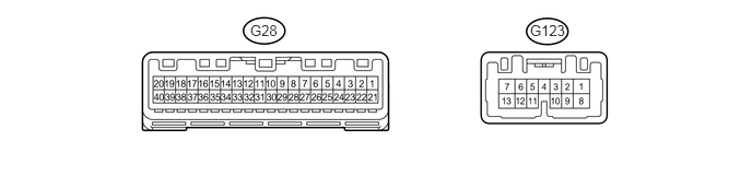
Inspect the Combination meter sub-assembly.
Measure the voltage of the wire harness side connectors.
| Terminal No. (Symbols) | Wiring Color | Terminal Description | Condition | Specified Condition |
|---|---|---|---|---|
| G123-5 (HAZ) - Body ground | GR - Body ground | Hazard warning signal switch input | Engine switch on (IG) and hazard warning signal switch off | 11 to 14 V |
| Engine switch on (IG) and hazard warning signal switch ON | Below 1 V | |||
| G123-10 (EL) - Body ground | P - Body ground | Turn LH signal | Headlight dimmer switch NORMAL position | 11 to 14 V |
| Headlight dimmer switch TURN LH position | Below 1 V | |||
| G123-9 (ER) - Body ground | SB - Body ground | Turn RH signal | Headlight dimmer switch NORMAL position | 11 to 14 V |
| Headlight dimmer switch TURN RH position | Below 1 V |
CHECK POWER BACK DOOR UNIT (POWER BACK DOOR ECU) (w/ Power back door)

Inspect the power back door unit (power back door ECU).
Measure the voltage and resistance of the wire harness side connectors.
| Terminal No. (Symbols) | Wiring Color | Terminal Description | Condition | Specified Condition |
|---|---|---|---|---|
| M24-3 (CTYO) - Body ground | R - W-B | Luggage compartment light drive output | Back door closed | Below 1 V |
| Back door open | 11 to 14 V | |||
| M24-11 (GND) - Body ground | W-B - Body ground | Ground | Always | Below 1 Ω |
| M24-20 (FUL) - Body ground | V - Body ground | Back door lock assembly (latch courtesy switch) signal circuit | Back door closed | 11 to 14 V |
| Back door open | Below 1 V |
CHECK HEADLIGHT LEVELING ECU ASSEMBLY

Inspect the headlight leveling ECU assembly.
Measure the voltage and resistance of the wire harness side connectors.
| Terminal No. (Symbols) | Wiring Color | Terminal Description | Condition | Specified Condition |
|---|---|---|---|---|
| A39-1 (IG) - A39-9 (E1) | B - W-B | Ignition power supply | Engine switch on (IG) | 11 to 14 V |
| A39-3 (HDLP) - A39-9 (E1) | R - W-B | Low beam headlight signal input | Low beam headlights off | 5 V or more |
| Low beam headlights on | Below 1.5 V | |||
| A39-5 (PRST) - A39-9 (E1) | BR - W-B | Initialization signal input terminal | Always | 4.75 to 5.25 V |
| A39-6 (WNG) - A39-9 (E1) | P - W-B | Warning message output | Warning message on | Below 1 V |
| Warning message off | 11 to 14 V | |||
| A39-9 (E1) - Body ground | W-B- Body ground | Ground | Always | Below 1 Ω |
| A39-10 (LR1+) - A39-9 (E1) | R - W-B | Leveling motor RH power supply | Engine switch on (IG) | 11 to 14 V |
| A39-11 (LL1+) - A39-9 (E1) | LG - W-B | Leveling motor LH power supply | Engine switch on (IG) | 11 to 14 V |
| A39-12 (SBR) - A39-21 (SGR) | V - W-B | Rear height control sensor power supply | Engine switch on (IG) | 4.75 to 5.25 V |
| A39-16 (SPDR) - A39-9 (E1) | B - W-B | Vehicle speed signal input | Vehicle is driven at approximately 30 km/h (19 mph) | Pulse generation (See waveform 1) |
| A39-17 (RHT) - A39-9 (E1) | P - W-B | Leveling motor RH operation signal input | With low beam headlights on, vehicle height not changed | 1 V or less |
| With low beam headlights on, vehicle height changed and maintained for more than 17 seconds | 1.0 to 14.4 V | |||
| A39-18 (LHT) - A39-9 (E1) | V - W-B | Leveling motor LH operation signal input | With low beam headlights on, vehicle height not changed | 1 V or less |
| With low beam headlights on, vehicle height changed and maintained for more than 17 seconds | 1.0 to 14.4 V | |||
| A39-19 (SHRL) - A39-21 (SGR) | GR - W-B | Rear height control sensor signal input | Engine switch on (IG) | Approximately 2.8 V |
| A39-21 (SGR) - A39-9 (E1) | B - W-B | Rear height control sensor ground | Always | Below 1 Ω |
| A39-23 (LR1-) - A39-9 (E1) | BR - W-B | Leveling motor RH ground | Always | Below 1 Ω |
| A39-24 (LL1-) - A39-9 (E1) | BE - W-B | Leveling motor LH ground | Always | Below 1 Ω |
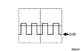
Waveform 1
| Item | Content |
| Terminal No. (Symbols) | A39-16 (SPDR) - A39-9 (E1) |
| Tool setting | 5 V/DIV., 20ms/DIV. |
| Condition | Vehicle is driven at approximately 30 km/h (19 mph) |
- HINT:
-
The pulse cycle becomes shorter as the vehicle speed increases.